


BOSM -5020-5Z Opposed-Head Boring Milling Machine

1. Equipment use:
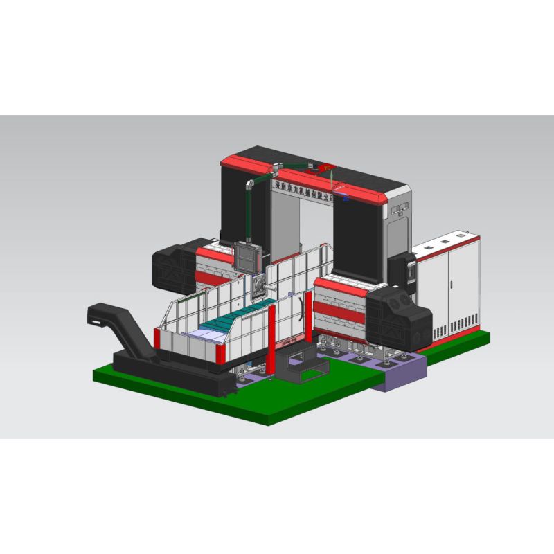
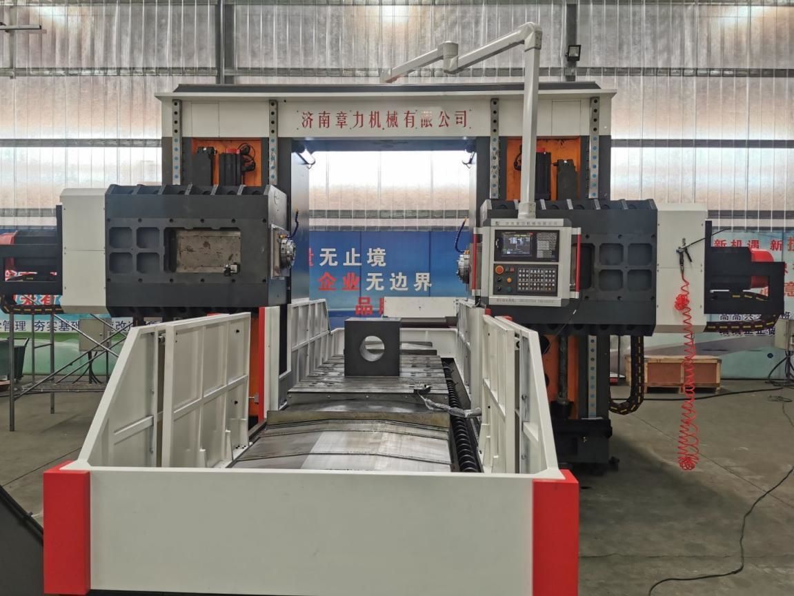
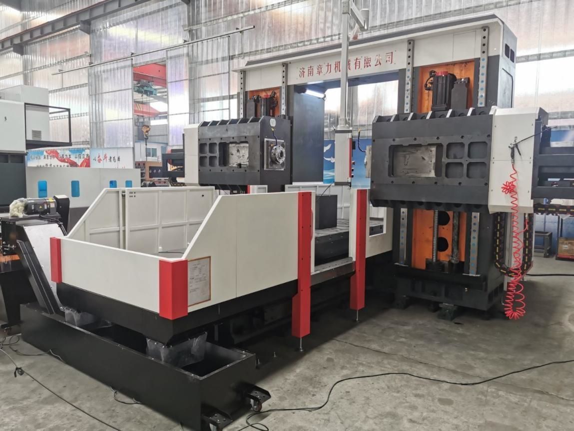
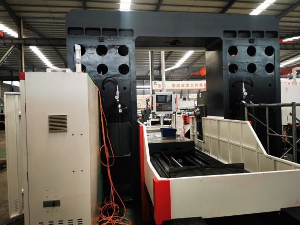
BOSM-5020-5Z CNC workbench mobile double-column head-to-head boring and milling machine is a special Machine for engineering machinery symmetrical workpieces. The Machine is equipped with a special movable workbench and two sets of horizontal rams, which can realize Drilling, milling, boring and other processing of the workpiece within the effective stroke range, the workpiece can be processed in place at one time (no need for secondary clamping), fast loading and unloading speed, fast positioning speed, high processing accuracy and high processing efficiency.
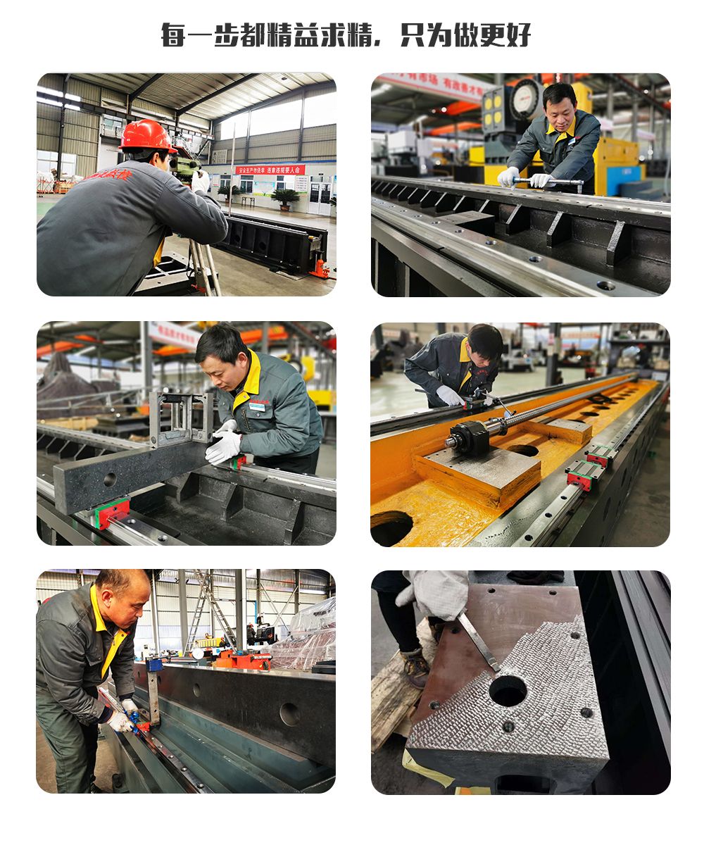
2. Equipment structure:
2.1. Main components of the Machine
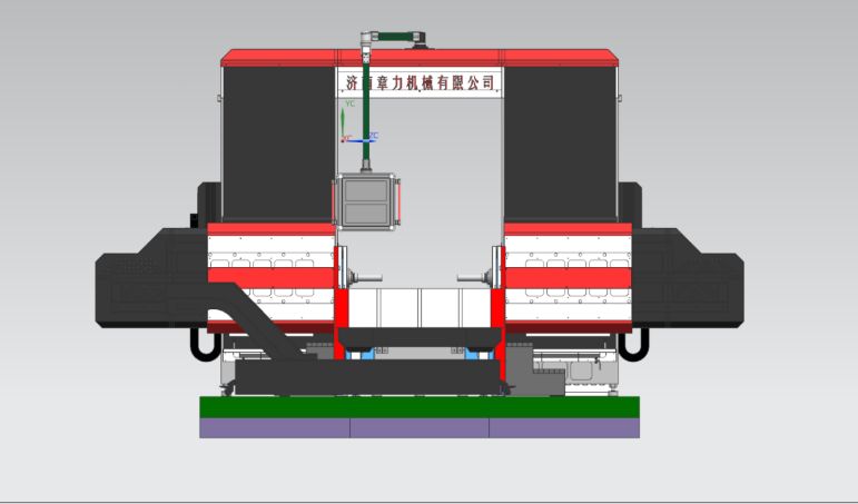
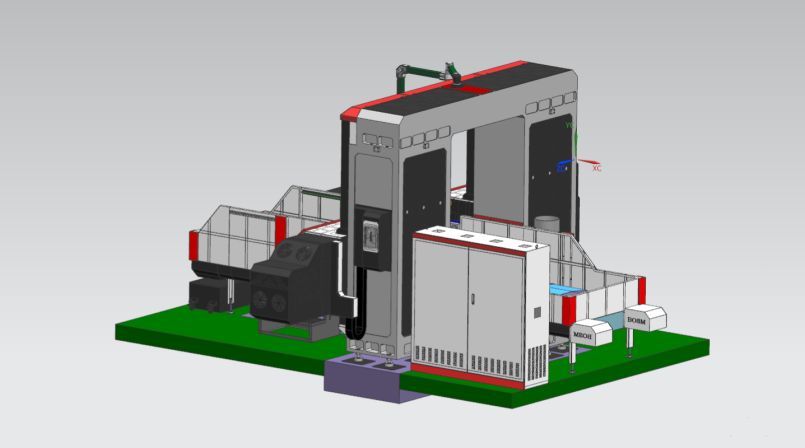
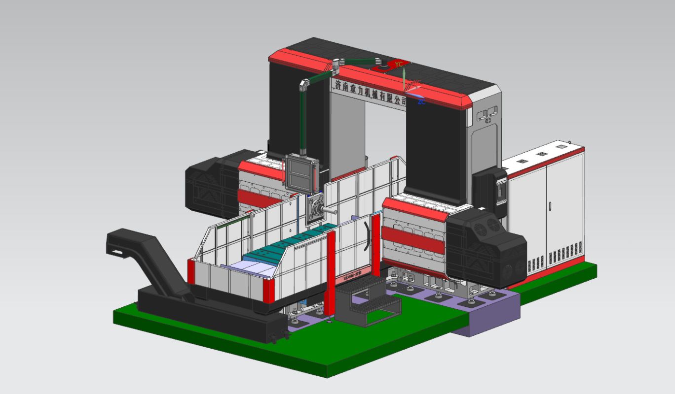
The bed, workbench, left and right columns, beams, gantry connecting beams, saddles, rams, etc., are all made of resin sand molding, high-quality gray iron 250 casting, annealed in hot sand pit → vibration aging → furnace annealing → vibration Aging→rough machining→vibration aging→furnace annealing→vibration aging→finishing, completely eliminate the negative stress of the parts, and keep the performance of the parts stable. The fixed bed, the left and right columns, the gantry, and the workbench move; the Machine has milling, boring Cutting, drilling, countersinking, tapping and other functions, the tool cooling method is external cooling, the Machine contains 5 feed axes, which can realize 4-axis linkage, 5-axis single-action, 2 power heads, the Machine axial and The power head is shown in the figure below.
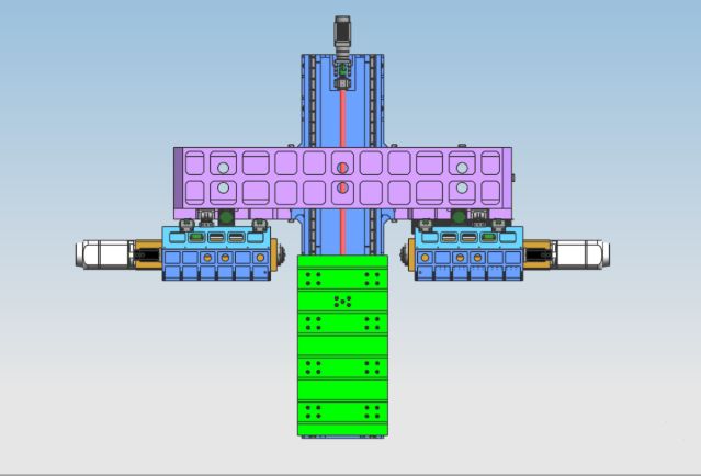
2.2. The main structure of the axial transmission feed part
2.2.1. X-axis: The worktable reciprocates laterally along the guide rail of the fixed bed.
X-axis transmission: AC servo motor and high-precision planetary reducer are used to drive the worktable through ball screw transmission to realize X-axis linear motion.
Guide rail form: lay two high-strength precision linear guide rails
2.2.2.Y1 axis: The power head and a ram are vertically installed on the front side of the column, and reciprocate left and right along the guide rail of the column.
Y1-axis transmission: AC servo motor is used to drive the ball screw to drive the saddle to move, and realize the Y1-axis linear motion.
Guide rail form: 4 pieces of 45 type linear guide rails.
2.2.3.Y2 axis: The second ram of the power head is installed vertically on the front side of the column, and reciprocates left and right along the guide rail of the column.
Y2-axis transmission: AC servo motor is used to drive the ball screw to drive the saddle movement to realize the linear movement of Y1-axis.
Guide rail form: 4 pieces of 45 type linear guide rails
2.2.4. Z1 axis: The power head sliding saddle is installed vertically on the front side of the right column, and reciprocates up and down along the column guide rail.
Z1-axis transmission: AC servo motor and high-precision planetary reducer are used to drive the ram to move through the ball screw to realize Z1-axis linear motion.
Guide rail form: 2 65 type linear guide rails
2.2.5.Z2 axis: The power head slide saddle is installed vertically on the front side of the right column, and reciprocates up and down along the column guide rail.
Z1-axis transmission: AC servo motor plus high-precision planetary reducer is used to drive the ram to move through the ball screw to realize Z2-axis linear motion.
Guide rail form: 2 65 type linear guide rails
High quality HT250 casting column 2 pieces of 65 type heavy-duty linear guide rails
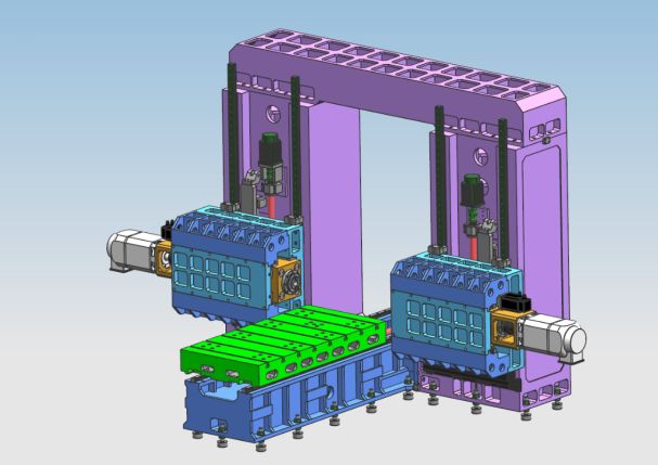
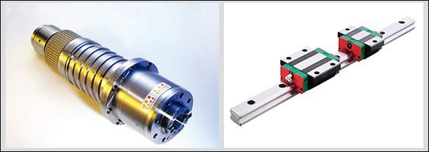
The boring and milling power head (including the power head 1 and 2) is a compound square ram, and the moving direction is guided by 4 linear roller guide rails. The drive uses an AC servo motor to drive the precision ball screw pair. The machine is equipped with a nitrogen balance bar. , Reduce the bearing capacity of the machine head on the screw and servo motor. The Z-axis motor has an automatic brake function. In the event of a power failure, the automatic brake will hold the motor shaft tightly so that it cannot rotate. When working, when the drill bit does not touch the workpiece, it will feed rapidly; when the drill bit touches the workpiece, it will automatically switch to working feed. When the drill bit penetrates the workpiece, it will automatically switch to fast rewind; when the end of the drill bit leaves the workpiece and reaches the set position, it will move to the next hole position to realize automatic circulation. And it can realize the functions of blind hole drilling, milling, chamfering, chip breaking, automatic chip removal, etc., which improves labor productivity.
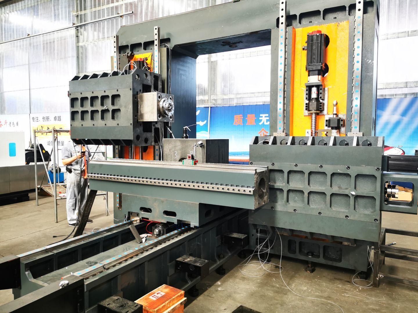
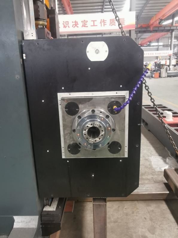
The 500mm stroke compound square ram power head uses linear guides instead of traditional inserts to greatly improve the guiding accuracy while retaining the rigidity of the square ram.
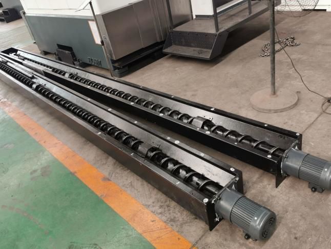
2.3. Chip removal and cooling
There are spiral and flat chain chip conveyors installed on both sides under the workbench, and the chips can be automatically conveyed to the chip conveyor at the end through two stages of spiral and chain plates to realize civilized production. There is a cooling pump in the coolant tank of the chip conveyor, which can be used for external cooling of the tool to ensure the performance and service life of the tool, and the coolant can be recycled.
3. Full digital numerical control system:
3.1. With chip breaking function, chip breaking time and chip breaking cycle can be set on the man-machine interface.
3.2. Equipped with the tool lifting function, the tool lifting distance can be set on the man-machine interface. When the distance is reached, the tool is lifted quickly, then the chips are thrown away, and then it is fast forwarded to the drilling surface and automatically converted to work.
3.3. Centralized operation control box and hand-held unit adopt numerical control system and are equipped with USB interface and LCD liquid crystal display. In order to facilitate programming, storage, display and communication, the operation interface has functions such as man-machine dialogue, error compensation, and automatic alarm.
3.4. The equipment has the function of previewing and re-inspecting the hole position before processing, and the operation is very convenient.
4. Automatic lubrication
Machine precision linear guide rail pairs, precision ball screw pairs and other high-precision motion pairs are equipped with automatic lubrication systems. The automatic lubricating pump outputs pressure oil, and the quantitative lubricator oil chamber enters the oil. After the oil chamber is filled with oil, when the system pressure rises to 1.4-1.75Mpa, the pressure switch in the system is closed, the pump stops, and the unloading valve unloads at the same time. When the oil pressure in the road drops below 0.2Mpa, the quantitative lubricator starts to fill the lubricating point and completes one oil filling. Due to the accurate oil supply of the quantitative oil injector and the detection of the system pressure, the oil supply is reliable, ensuring that there is an oil film on the surface of each kinematic pair, reducing friction and wear, and preventing the damage to the internal structure caused by overheating. , to ensure the accuracy and life of the Machine. Compared with the sliding guide rail pair, the rolling linear guide rail pair used in this Machine has a series of advantages:
①The motion sensitivity is high, the friction coefficient of the rolling guide rail is small, only 0.0025~0.01, and the driving power is greatly reduced, which is only equivalent to 1/10 of ordinary machinery.
② The difference between dynamic and static friction is very small, and the follow-up performance is excellent, that is, the time interval between the driving signal and the mechanical action is extremely short, which is conducive to improving the response speed and sensitivity of the numerical control system.
③It is suitable for high-speed linear motion, and its instantaneous speed is about 10 times higher than that of sliding guide rails.
④ It can realize gapless movement and improve the movement rigidity of the mechanical system.
⑤Produced by professional manufacturers, it has high precision, good versatility and easy maintenance.
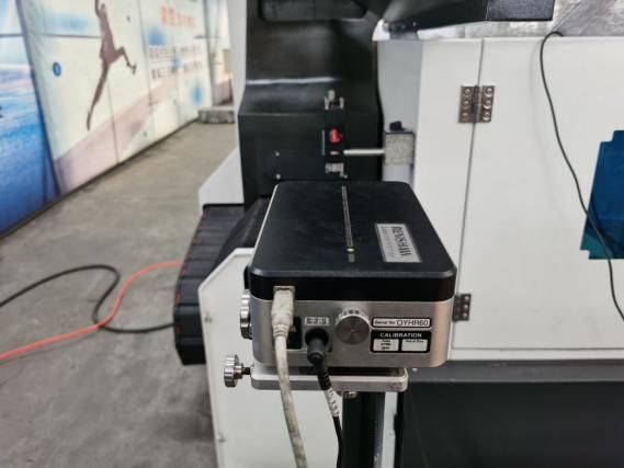
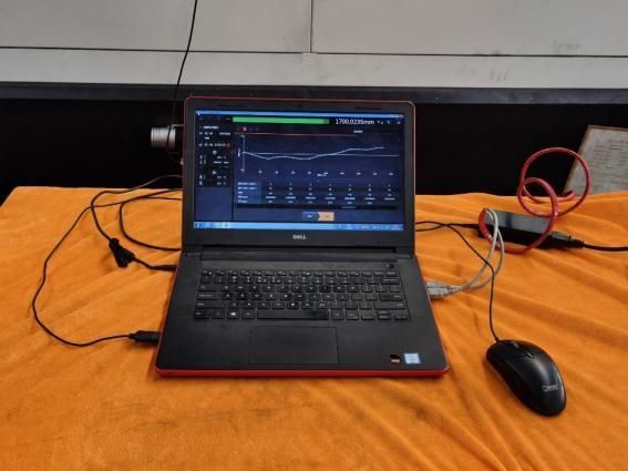
5.Three-axis laser inspection:
Each machine of Bosman is calibrated by the laser interferometer of RENISHAW company in the United Kingdom to accurately inspect and compensate the pitch error, backlash, positioning accuracy, repeat positioning accuracy, etc., to ensure the dynamic, static stability and processing accuracy of the machine . Ballbar inspection Each machine uses a ballbar from British RENISHAW company to calibrate the true circle accuracy and machine geometric accuracy, and conduct circular cutting experiments at the same time to ensure the 3D machining accuracy and circular accuracy of the machine.
6. Machine use environment:
6.1. Equipment use environment requirements
Maintaining a constant level of ambient temperature is an essential factor for precision machining.
(1) Available ambient temperature requirements are -10°C to 35°C, when the ambient temperature is 20°C, the humidity should be 40% to 75%.
(2) In order to keep the static accuracy of the Machine within the specified range, the optimum ambient temperature is required to be 15°C to 25°C, and the temperature difference shall not exceed ±2°C/24h.
6.2. Power supply voltage: 3 phases, 380V, within the range of ±10% voltage fluctuation, power supply frequency: 50HZ.
6.3. If the voltage in the area of use is unstable, the Machine should be equipped with a stabilized power supply to ensure the normal operation of the Machine.
6.4. The Machine should have reliable grounding: the grounding wire is a copper wire, the wire diameter should not be less than 10mm², and the grounding resistance should be less than 4 ohms.
6.5. In order to ensure the normal working performance of the equipment, if the compressed air of the air source cannot meet the requirements of the air source, a set of air source purification device (dehumidification, degreasing, filtering) should be added before the air intake of the Machine.
6.6. Keep the equipment away from direct sunlight, vibration and heat sources, high-frequency generators, electric welding machines, etc., so as to avoid Machine production failure or loss of Machine accuracy.
7.Technical parameters:
|
Model |
5020-5Z |
|
|
Maximum processing workpiece size |
Length × width × height (mm) |
5000×2000×2500 |
|
Gantry maximum feed |
Width (mm) |
2300 |
|
working desk size |
Length X Width (mm) |
5000*2000 |
|
Table travel |
Workbench moves back and forth (mm) |
5000 |
|
Double ram lift up and down |
Up and down stroke of ram (mm) |
2500 |
|
Horizontal ram type drilling head power head one two |
Quantity (2) |
2 |
|
Horizontal ram type drilling head power head one two |
Spindle taper |
BT50 |
|
Spindle speed (r/min) |
30~5000 |
|
|
Servo spindle motor power (kw) |
37*2 |
|
|
The distance between the centers of the nose ends of the two spindles (mm) |
1500-2500mm |
|
|
Left and right stroke of single ram (mm) |
500 |
|
|
Left and right stroke of double ram (mm) |
1000 |
|
| Bidirectional Positioning Accuracy |
300mm*300mm |
±0.025 |
| Bi-directional repeat positioning accuracy |
300mm*300mm |
±0.02 |
| Gross weight (t) |
(about)55 |
Gross weight (t) |
Products categories
-

VC Series High Rigidity CNC Machining Center wi...
-

HP Series Horizontal Moving Column Linear Guide...
-

HT Series Horizontal Moving Column Linear Guide...
-

VS Series Four-track Heavy Duty CNC Machining C...
-

V Series CNC Machining Center with High Rigidity
-

X Series Double Column CNC Machining Center
-

Horizontal 5-Axis CNC Machining Center TKG1600
-

CNC Vertical Turning and Milling Composite Cent...
-

High Speed CNC Machining Center GM Series
-

High Speed CNC Milling GT Series
-

Dual-Spindle CNC Lathe SK32
-

CNC Vertical Machining Center RFTV510 For Wheel...