


Double Spindle High Performance CNC Turning and Milling Compound Center 600/800/1200/1600/2000/3000 Series


Product Video
Product Configuration
Features
Turret Design Performance
The integrated positive Y-axis structure is highly rigid, heavy-duty, and has better performance than the interpolation Y-axis.
·Smoother and smoother plane contour processing
·Easier to process compound curved surfaces and contours
Compared with the "interpolation Y", the "positive Y" has obvious advantages in plane milling. The "positive Y" Y-axis movement is perpendicular to the X-axis and is a single-axis movement. The "interpolation Y" Y-axis movement is to interpolate a straight line through the simultaneous movement of the X-axis and the Y-axis. Compared with the "positive Y" for the flatness of the milling plane, the "positive Y" axis processing is obviously bright and smooth.
Direct Drive Synchronous Electric Spindle
High rigidity, high torque, higher efficiency, better finish, more precise indexing.
All major CNC turning machine parts are made of cast iron HT300 with extremely strong shock absorption capacity.
Features of CNC machine tools with direct-drive electric spindles
●Magnetic ring incremental encoder (sine and cosine) positioning accuracy: 20 arc seconds,
C-axis indexing accuracy: 40 arc seconds
●Fast start-stop response speed, saving machine tool time and effectively improving production capacity
●Small cutting load, energy saving and power saving, better protection of machine tools and extended service life
●Effectively eliminate spindle vibration, good balancing effect, good finish, and improve the surface finish of workpieces
(Advantages of turning instead of grinding, hard turning appearance, surface roughness Ra 0.2μm)
· The CNC turning center spindle motor is equipped with a cooling system to suppress the influence of thermal displacement and ensure that the spindle continues to work at a constant temperature.
(The nose end run out accuracy is within 0.002mm, ensuring more stable accuracy)
· Rear-mounted direct-drive synchronous spindle, more convenient installation and maintenance
· A2-5: 7016AC-front two rear two
· A2-6: front NN3020+100BAR10S, rear NN3018
A2-8: front NN3024+BT022B*2, rear NN3022
Heavy-Duty Cast Iron Base And Components
All castings are optimized using finite element analysis (FEA) to reduce distortion and lift-off shock absorption capacity. The castings of the major series of CNC lathe turning center are reinforced with ribs to enhance rigidity and thermal stability. Compact and symmetrical headstock and tailstock castings further enhance rigidity and ensure high positioning accuracy and repeatability.
Technical Specifications
|
Item |
Name |
Unit |
800MS |
800MSY |
600MS |
600MSY |
1200MS |
|
Travel |
Max. bed rotation diameter |
mm |
Φ700 |
Φ800 |
Φ700 |
Φ800 |
Φ700 |
|
Max. machining diameter |
mm |
Φ540 |
Φ360 |
Φ540 |
Φ360 |
Φ530 |
|
|
Max. rotation diameter on tool holder |
mm |
Φ350 |
Φ450 |
Φ350 |
Φ450 |
Φ350 |
|
|
Max. processing length |
mm |
770 |
770 |
570 |
570 |
1050 |
|
|
Distance between two centers |
mm |
770 |
770 |
570 |
570 |
1030 |
|
|
spindle Cylinder Chuck |
Spindle nose |
ASA |
A2-6 |
A2-6 |
A2-6 |
A2-6 |
A2-8 |
|
Hydraulic cylinder/chuck |
Inch |
8’’ |
8’’ |
8’’ |
8’’ |
10° |
|
|
Spindle through hole diameter |
mm |
Φ79/66 |
Φ79/66 |
Φ79/66 |
Φ79/66 |
Φ86 |
|
|
Max. rod through hole diameter |
mm |
Φ65/52 |
Φ66/52 |
Φ65/52 |
Φ65/52 |
Φ76 |
|
|
Spindle Max. speed |
rpm |
4300 |
4000/4500 |
4300 |
4300 |
2500 |
|
|
Spindle motor power |
kw |
18/22 |
18/22 |
18/22 |
18/22 |
17 |
|
|
Spindle motor torque |
Nm |
91-227 |
91/227 |
91-227 |
91-227 |
170/400 |
|
|
Sub-spindle Cylinder Chuck
|
Sub-Spindle nose |
ASA |
A2-6 |
A2-6 |
A2-6 |
A2-6 |
A2-6 |
|
Sub-Hydraulic cylinder/chuck |
Inch |
8” |
8” |
8” |
8” |
8" |
|
|
Sub-Spindle through hole diameter |
mm |
Φ66 |
Φ66 |
Φ79/66 |
Φ66 |
Φ66 |
|
|
Sub-Max. rod through hole diameter |
mm |
Φ52 |
Φ52 |
Φ52 |
Φ52 |
Φ52 |
|
|
Sub-Spindle Max. speed |
rpm |
4300 |
4300 |
4300 |
4300 |
4300 |
|
|
Sub-Spindle motor power |
kw |
18/22 |
18/22 |
18/22 |
18/22 |
18/22 |
|
|
X/ZN/S axis feed parameters |
X motor power |
kw |
3 |
3 |
3 |
3 |
3 |
|
Y motor power |
kw |
- |
1.8 |
- |
1.8 |
- |
|
|
Z motor power |
kw |
3 |
3 |
3 |
3 |
3 |
|
|
S motor power |
Kw |
3 |
3 |
3 |
3 |
- |
|
|
X axis travel |
mm |
320 |
215 |
315 |
215 |
313 |
|
|
Y axis travel |
mm |
- |
- |
- |
100±50 |
- |
|
|
Z axis travel |
mm |
80 |
820 |
620 |
620 |
1210 |
|
|
X/Z axis rail specifications |
spec |
45 roller |
45 roller |
45 roller |
45 roller |
45 roller |
|
|
Y axis rail specifications |
spec |
- |
- |
- |
- |
- |
|
|
S axis travel |
mm |
770 |
770 |
570 |
570 |
880 |
|
|
X axis fast move |
Mm/min |
24 |
24 |
24 |
24 |
24 |
|
|
Z axis fast move |
Mm/min |
24 |
24 |
24 |
24 |
24 |
|
|
Y axis fast move |
Mm/min |
- |
8 |
- |
8 |
- |
|
|
S axis fast move |
Mm/min |
24 |
24 |
24 |
24 |
24 |
|
|
Servo power Turret parameters |
Power turret type |
/ |
Servo turret |
Servo turret |
Servo turret |
Servo turret |
Servo turret |
|
Tool station |
/ |
BMT55 |
BMT55MY |
BMT55 |
BMT55MY |
BMT65 |
|
|
M motor power |
kw |
5.5 |
5.5 |
5.5 |
5.5 |
7.5 |
|
|
M axis motor torque |
Nm |
35 |
35 |
35 |
35 |
47.8 |
|
|
Power head Max. speed |
rpm |
6000 |
6000 |
6000 |
6000 |
6000 |
|
|
Outer diameter tool holder specifications |
mm |
25*25 |
25*25 |
25*25 |
25*25 |
25*25 |
|
|
Inner diameter tool holder specifications |
mm |
Φ40 |
Φ50 |
Φ40 |
Φ40 |
Φ50 |
|
|
Adjacent tool change time |
sec |
0.15 |
0.15 |
0.15 |
0.15 |
0.15 |
|
|
Positioning accuracy |
/ |
±0.005 |
±0.005 |
±0.005 |
±0.005 |
±0.005 |
|
|
Repeat positioning accuracy |
/ |
±0.003 |
±0.003 |
±0.003 |
±0.003 |
±0.003 |
|
|
Tailstock parameters |
Programmable hydraulic tailstock |
/ |
- |
- |
- |
- |
- |
|
Tailstock Max. travel |
mm |
- |
|||||
|
Sleeve diameter |
mm |
- |
|||||
|
Sleeve travel |
mm |
- |
|||||
|
Sleeve taper |
/ |
- |
|||||
|
Dimensions |
Overall dimensions |
m |
3100*2250*2100 |
3500*2250*2100 |
3100*2110*1800 |
3100*2250*2100 |
3900*2400*2100 |
|
Machine weight approx. |
kg |
5600 |
7000 |
5500 |
5600 |
7600 |
|
|
Other |
Cutting fluid tank volume |
L |
250 |
250 |
250 |
250 |
300 |
|
Cooling water pump power |
kw |
0.75 |
0.75 |
0.75 |
0.75 |
0.75 |
|
|
Hydraulic unit box volume |
L |
40 |
40 |
40 |
40 |
40 |
|
|
Hydraulic oil pump motor power |
kw |
1.5 |
1.5 |
1.5 |
1.5 |
1.5 |
|
|
Lubricating oil tank volume |
L |
2 |
2 |
2 |
2 |
2 |
|
|
Automatic lubrication pump motor power |
kw |
50 |
50 |
50 |
50 |
50 |
|
Item |
Name |
Unit |
1200MSY |
1600MS |
1600MSY |
2000MS |
2000MSY |
|
Travel |
Max. bed rotation diameter |
mm |
Φ800 |
Φ700 |
Φ800 |
Φ700 |
Φ800 |
|
Max. machining diameter |
mm |
Φ400 |
Φ530 |
Φ400 |
Φ530 |
Φ400 |
|
|
Max. rotation diameter on tool holder |
mm |
Φ450 |
Φ350 |
Φ450 |
Φ350 |
Φ450 |
|
|
Max. processing length |
mm |
970 |
1450 |
1370 |
2030 |
2030 |
|
|
Distance between two centers |
mm |
1030 |
1030 |
1030 |
2030 |
2030 |
|
|
spindle Cylinder Chuck |
Spindle nose |
ASA |
A2-8 |
A2-8 |
A2-8 |
A2-8 |
A2-8 |
|
Hydraulic cylinder/chuck |
Inch |
10" |
10° |
10" |
10" |
10" |
|
|
Spindle through hole diameter |
mm |
Φ86 |
Φ86 |
Φ86 |
Φ86 |
Φ86 |
|
|
Max. rod through hole diameter |
mm |
Φ76 |
Φ76 |
Φ76 |
Φ76 |
Φ76 |
|
|
Spindle Max. speed |
rpm |
2500 |
2500 |
2500 |
2500 |
2500 |
|
|
Spindle motor power |
kw |
17 |
17 |
17 |
17 |
17 |
|
|
Spindle motor torque |
Nm |
170/400 |
170/400 |
170/400 |
170/400 |
170/400 |
|
|
Sub-spindle Cylinder Chuck
|
Sub-Spindle nose |
ASA |
A2-6 |
A2-6 |
A2-6 |
A2-6 |
A2-6 |
|
Sub-Hydraulic cylinder/chuck |
Inch |
8* |
8" |
8* |
8" |
8* |
|
|
Sub-Spindle through hole diameter |
mm |
Φ66 |
Φ66 |
Φ66 |
Φ66 |
Φ66 |
|
|
Sub-Max. rod through hole diameter |
mm |
Φ52 |
Φ52 |
Φ52 |
Φ52 |
Φ52 |
|
|
Sub-Spindle Max. speed |
rpm |
4300 |
4300 |
4300 |
4300 |
4300 |
|
|
Sub-Spindle motor power |
kw |
18/22 |
18/22 |
18/22 |
18/22 |
18/22 |
|
|
X/ZN/S axis feed parameters |
X motor power |
kw |
3 |
3 |
3 |
3 |
3 |
|
Y motor power |
kw |
1.8 |
- |
1.8 |
- |
1.8 |
|
|
Z motor power |
kw |
3 |
3 |
3 |
3 |
3 |
|
|
S motor power |
Kw |
- |
3 |
3 |
3 |
3 |
|
|
X axis travel |
mm |
235 |
313 |
235 |
313 |
235 |
|
|
Y axis travel |
mm |
100±50 |
- |
120±60 |
- |
120±60 |
|
|
Z axis travel |
mm |
1100 |
1620 |
1500 |
2220 |
2100 |
|
|
X/Z axis rail specifications |
spec |
45 roller |
45 roller |
45 roller |
45 roller |
45 roller |
|
|
Y axis rail specifications |
spec |
- |
- |
- |
- |
- |
|
|
S axis travel |
mm |
880 |
880 |
880 |
2030 |
2030 |
|
|
X axis fast move |
Mm/min |
24 |
24 |
24 |
24 |
24 |
|
|
Z axis fast move |
Mm/min |
24 |
24 |
24 |
24 |
24 |
|
|
Y axis fast move |
Mm/min |
8 |
- |
8 |
- |
8 |
|
|
S axis fast move |
Mm/min |
24 |
24 |
24 |
24 |
24 |
|
|
Servo power Turret parameters |
Power turret type |
/ |
Servo turret |
Servo turret |
Servo turret |
Servo turret |
Servo turret |
|
Tool station |
/ |
BMT65MY |
BMT65 |
BMT65MY |
BMT65 |
BMT65MY |
|
|
M motor power |
kw |
7.5 |
7.5 |
7.5 |
7.5 |
7.5 |
|
|
M axis motor torque |
Nm |
47.8 |
47.8 |
47.8 |
47.8 |
47.8 |
|
|
Power head Max. speed |
rpm |
6000 |
6000 |
6000 |
6000 |
6000 |
|
|
Outer diameter tool holder specifications |
mm |
25*25 |
25*25 |
25*25 |
25*25 |
25*25 |
|
|
Inner diameter tool holder specifications |
mm |
Φ50 |
Φ50 |
Φ50 |
Φ50 |
Φ50 |
|
|
Adjacent tool change time |
sec |
0.15 |
0.15 |
0.15 |
0.15 |
0.15 |
|
|
Positioning accuracy |
/ |
±0.005 |
±0.005 |
±0.005 |
±0.005 |
±0.005 |
|
|
Repeat positioning accuracy |
/ |
±0.003 |
±0.003 |
±0.003 |
±0.003 |
±0.003 |
|
|
Tailstock parameters |
Programmable hydraulic tailstock |
/ |
- |
- |
- |
- |
- |
|
Tailstock Max. travel |
mm |
- |
- |
- |
- |
- |
|
|
Sleeve diameter |
mm |
- |
- |
- |
- |
- |
|
|
Sleeve travel |
mm |
- |
- |
- |
- |
- |
|
|
Sleeve taper |
/ |
- |
- |
- |
- |
- |
|
|
Dimensions |
Overall dimensions |
m |
3900*2400*2100 |
4300*2110*2100 |
4300*2110*2100 |
4300*2110*2100 |
4300*2110*2100 |
|
Machine weight approx. |
kg |
7800 |
8400 |
8500 |
8400 |
8500 |
|
|
Other |
Cutting fluid tank volume |
L |
300 |
350 |
350 |
350 |
350 |
|
Cooling water pump power |
kw |
0.75 |
0.75 |
0.75 |
0.75 |
0.75 |
|
|
Hydraulic unit box volume |
L |
40 |
40 |
40 |
40 |
40 |
|
|
Hydraulic oil pump motor power |
kw |
1.5 |
1.5 |
1.5 |
1.5 |
1.5 |
|
|
Lubricating oil tank volume |
L |
2 |
2 |
2 |
2 |
2 |
|
|
Automatic lubrication pump motor power |
kw |
50 |
50 |
50 |
50 |
50 |
|
Item |
Name |
Unit |
3000MS |
3000MSY |
600MSY |
800MSY |
1200MSY |
|
Travel |
Max. bed rotation diameter |
mm |
Φ700 |
Φ800 |
Φ800 |
Φ800 |
Φ800 |
|
Max. machining diameter |
mm |
Φ530 |
Φ400 |
Φ320 |
Φ320 |
Φ320 |
|
|
Max. rotation diameter on tool holder |
mm |
Φ350 |
Φ450 |
Φ450 |
Φ450 |
Φ450 |
|
|
Max. processing length |
mm |
3030 |
3030 |
510 |
710 |
970 |
|
|
Distance between two centers |
mm |
3030 |
3030 |
570 |
770 |
1030 |
|
|
spindle Cylinder Chuck |
Spindle nose |
ASA |
A2-8 |
A2-8 |
A2-6 |
A2-6 |
A2-8 |
|
Hydraulic cylinder/chuck |
Inch |
10" |
10" |
8" |
8" |
10" |
|
|
Spindle through hole diameter |
mm |
Φ86 |
Φ86 |
Φ79/66 |
Φ79/66 |
Φ86 |
|
|
Max. rod through hole diameter |
mm |
Φ76 |
Φ76 |
Φ66/52 |
Φ66/52 |
Φ76 |
|
|
Spindle Max. speed |
rpm |
2500 |
2500 |
4300 |
4300 |
2500 |
|
|
Spindle motor power |
kw |
17 |
17 |
18/22 |
18/22 |
17 |
|
|
Spindle motor torque |
Nm |
170/400 |
170/400 |
91-227 |
91/227 |
170/400 |
|
|
Sub-spindle Cylinder Chuck
|
Sub-Spindle nose |
ASA |
A2-6 |
A2-6 |
A2-6 |
A2-6 |
A2-6 |
|
Sub-Hydraulic cylinder/chuck |
Inch |
8" |
8* |
8" |
8" |
8* |
|
|
Sub-Spindle through hole diameter |
mm |
Φ66 |
Φ66 |
Φ66 |
Φ66 |
Φ66 |
|
|
Sub-Max. rod through hole diameter |
mm |
Φ52 |
Φ52 |
Φ52 |
Φ52 |
Φ52 |
|
|
Sub-Spindle Max. speed |
rpm |
4300 |
4300 |
4300 |
4300 |
4300 |
|
|
Sub-Spindle motor power |
kw |
18/22 |
18/22 |
18/22 |
18/22 |
18/22 |
|
|
X/ZN/S axis feed parameters |
X motor power |
kw |
3 |
3 |
3 |
3 |
3 |
|
Y motor power |
kw |
- |
1.8 |
1.8 |
1.8 |
1.8 |
|
|
Z motor power |
kw |
3 |
3 |
3 |
3 |
3 |
|
|
S motor power |
Kw |
3 |
3 |
- |
3 |
3 |
|
|
X axis travel |
mm |
313 |
235 |
210 |
210 |
210 |
|
|
Y axis travel |
mm |
- |
120±60 |
120±50 |
120±50 |
120±60 |
|
|
Z axis travel |
mm |
3220 |
3100 |
620 |
820 |
1100 |
|
|
X/Z axis rail specifications |
spec |
45 roller |
45 roller |
45 roller |
45 roller |
45 roller |
|
|
Y axis rail specifications |
spec |
- |
- |
- |
- |
- |
|
|
S axis travel |
mm |
3080 |
3080 |
- |
770 |
880 |
|
|
X axis fast move |
Mm/min |
24 |
24 |
8 |
8 |
8 |
|
|
Z axis fast move |
Mm/min |
24 |
24 |
24 |
24 |
24 |
|
|
Y axis fast move |
Mm/min |
- |
8 |
8 |
8 |
8 |
|
|
S axis fast move |
Mm/min |
24 |
24 |
24 |
24 |
24 |
|
|
Servo power Turret parameters |
Power turret type |
/ |
Servo turret |
Servo turret |
Servo turret |
Servo turret |
Servo turret |
|
Tool station |
/ |
BMT65 |
BMT65MY |
BMT55MY-16T |
BMT55MY-16T |
BMT55MY-16T |
|
|
M motor power |
kw |
7.5 |
7.5 |
5.5 |
5.5 |
7.5 |
|
|
M axis motor torque |
Nm |
47.8 |
47.8 |
35 |
35 |
47.8 |
|
|
Power head Max. speed |
rpm |
6000 |
6000 |
6000 |
6000 |
6000 |
|
|
Outer diameter tool holder specifications |
mm |
25*25 |
25*25 |
25*25 |
25*25 |
25*25 |
|
|
Inner diameter tool holder specifications |
mm |
Φ50 |
Φ50 |
Φ50 |
Φ50 |
Φ50 |
|
|
Adjacent tool change time |
sec |
0.2 |
0.2 |
0.15 |
0.15 |
0.15 |
|
|
Positioning accuracy |
/ |
±0.005 |
±0.005 |
±0.005 |
±0.005 |
±0.005 |
|
|
Repeat positioning accuracy |
/ |
±0.003 |
±0.003 |
±0.003 |
±0.003 |
±0.003 |
|
|
Tailstock parameters |
Programmable hydraulic tailstock |
/ |
- |
- |
- |
- |
- |
|
Tailstock Max. travel |
mm |
- |
- |
- |
- |
- |
|
|
Sleeve diameter |
mm |
- |
- |
- |
- |
- |
|
|
Sleeve travel |
mm |
- |
- |
- |
- |
- |
|
|
Sleeve taper |
/ |
- |
- |
- |
- |
- |
|
|
Dimensions |
Overall dimensions |
m |
6200*2300*2160 |
6200*2300*2160 |
3100*2250*2100 |
3500*2250*2100 |
3900*2400*2100 |
|
Machine weight approx. |
kg |
15000 |
15000 |
5600 |
7000 |
7800 |
|
|
Other |
Cutting fluid tank volume |
L |
485 |
485 |
250 |
250 |
300 |
|
Cooling water pump power |
kw |
0.75 |
0.75 |
0.75 |
0.75 |
0.75 |
|
|
Hydraulic unit box volume |
L |
40 |
40 |
40 |
40 |
40 |
|
|
Hydraulic oil pump motor power |
kw |
1.5 |
1.5 |
1.5 |
1.5 |
1.5 |
|
|
Lubricating oil tank volume |
L |
2 |
2 |
2 |
2 |
2 |
|
|
Automatic lubrication pump motor power |
kw |
50 |
50 |
50 |
50 |
50 |
Configuration Introduction
FANUC CNC
High Processing Performance
FANUC 0i-TF PLUS system has powerful high-efficiency processing technology and intelligent servo control technology; high-efficiency processing technology shortens the sequential processing time of external signals according to the acceleration and deceleration of the action state and maximizes the use of servo capabilities, thereby reducing the processing program cycle time; intelligent servo control refers to a servo control function group that can self-optimize and adjust in real time as the CNC milling turning center conditions such as load and temperature change, achieving high-speed and high-precision processing.
High Ease Of Use
FANUC 0i-TF PLUS system has a large-capacity program memory, CF card can be used as program memory, USB program can be run with one click, CNC-QSSR function helps high precision cnc turning center quickly and easily import robots, and the optional system IHMI function provides comprehensive support for work on the processing site, and provides tool information integrated management, processing time prediction, interactive dialogue programming, mechanical collision avoidance, processing data collection, maintenance management and other functions required for each process in the process of "planning", "processing" and "improvement".
High Operation Rate
The IOlinki and FSSB of FANUC Oi-TF PLUS have rich fault detection functions, which can determine the power failure of the I/O module or servo amplifier and the location of the communication cable disconnection. In addition, I/Olinki can detect the output short circuit of each DO point; in addition, the fault diagnosis function can obtain various diagnostic information on the CNC screen that helps to judge the system status when the alarm occurs, helping users to quickly repair the problem area.
THK Ball Screw
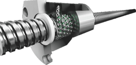
·C3 grade, using high-precision ball screw, with nut pre-loading and screw pre-tensioning treatment to pre-eliminate backlash and temperature rise elongation, showing excellent positioning and repeatability accuracy.
·Servo motor direct drive to reduce backlash error.
THK Roller Linear Guide
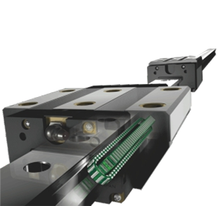
·P grade ultra-high rigidity SRG precision grade, linear guide zero clearance, arc cutting, bevel cutting, surface texture is relatively uniform. Suitable for high-speed operation, greatly reducing the driving horsepower required for machine tools.
·Rolling instead of sliding, small friction loss, sensitive response, high positioning accuracy. It can bear the load in the moving direction at the same time, and the track contact surface is still in multi-point contact during the load, and the cutting rigidity will not be reduced.
·Easy to assemble, strong interchangeability, and simple lubrication structure; the wear amount is very small and the service life is long.
SKF Bearing/Oiling Machine
·Automatic lubricator meets the needs of various applications, suitable for various working conditions, reliable products, flexible use.
·Turning center meet the needs of bearing lubrication in high temperature, strong vibration and dangerous environment.
Each lubrication point uses a volumetric proportional distributor to control the lubrication amount, and the machine can be controlled by PLC to accurately supply oil.
Turret Design Performance
The integrated positive Y-axis structure is highly rigid, heavy-duty, and has better performance than the interpolation Y-axis.
·Smoother and smoother plane contour processing
·Easier to process compound curved surfaces and contours
Compared with the “interpolation Y”, the “positive Y” has obvious advantages in plane milling. The “positive Y” Y-axis movement is perpendicular to the X-axis and is a single-axis movement. The “interpolation Y” Y-axis movement is to interpolate a straight line through the simultaneous movement of the X-axis and the Y-axis. Compared with the “positive Y” for the flatness of the milling plane, the “positive Y” axis processing is obviously bright and smooth.
Direct Drive Synchronous Electric Spindle
High rigidity, high torque, higher efficiency, better finish, more precise indexing.
All major machine parts are made of cast iron HT300 with extremely strong shock absorption capacity.
Features of machine tools with direct-drive electric spindles
●Magnetic ring incremental encoder (sine and cosine) positioning accuracy: 20 arc seconds,
C-axis indexing accuracy: 40 arc seconds
●Fast start-stop response speed, saving machine tool time and effectively improving production capacity
●Small cutting load, energy saving and power saving, better protection of machine tools and extended service life
●Effectively eliminate spindle vibration, good balancing effect, good finish, and improve the surface finish of workpieces
(Advantages of turning instead of grinding, hard turning appearance, surface roughness Ra 0.2μm)
· The spindle motor is equipped with a cooling system to suppress the influence of thermal displacement and ensure that the spindle continues to work at a constant temperature.
(The nose end run out accuracy is within 0.002mm, ensuring more stable accuracy)
· Rear-mounted direct-drive synchronous spindle, more convenient installation and maintenance
· A2-5: 7016AC-front two rear two
· A2-6: front NN3020+100BAR10S, rear NN3018
A2-8: front NN3024+BT022B*2, rear NN3022
Heavy-Duty Cast Iron Base And Components
All castings are optimized using finite element analysis (FEA) to reduce distortion and lift-off shock absorption capacity. The castings of the major series of lathes are reinforced with ribs to enhance rigidity and thermal stability. Compact and symmetrical headstock and tailstock castings further enhance rigidity and ensure high positioning accuracy and repeatability.
|
Item |
Name |
Unit |
800MS |
800MSY |
600MS |
600MSY |
1200MS |
|
Travel |
Max. bed rotation diameter |
mm |
Φ700 |
Φ800 |
Φ700 |
Φ800 |
Φ700 |
|
Max. machining diameter |
mm |
Φ540 |
Φ360 |
Φ540 |
Φ360 |
Φ530 |
|
|
Max. rotation diameter on tool holder |
mm |
Φ350 |
Φ450 |
Φ350 |
Φ450 |
Φ350 |
|
|
Max. processing length |
mm |
770 |
770 |
570 |
570 |
1050 |
|
|
Distance between two centers |
mm |
770 |
770 |
570 |
570 |
1030 |
|
|
spindle Cylinder Chuck |
Spindle nose |
ASA |
A2-6 |
A2-6 |
A2-6 |
A2-6 |
A2-8 |
|
Hydraulic cylinder/chuck |
Inch |
8’’ |
8’’ |
8’’ |
8’’ |
10° |
|
|
Spindle through hole diameter |
mm |
Φ79/66 |
Φ79/66 |
Φ79/66 |
Φ79/66 |
Φ86 |
|
|
Max. rod through hole diameter |
mm |
Φ65/52 |
Φ66/52 |
Φ65/52 |
Φ65/52 |
Φ76 |
|
|
Spindle Max. speed |
rpm |
4300 |
4000/4500 |
4300 |
4300 |
2500 |
|
|
Spindle motor power |
kw |
18/22 |
18/22 |
18/22 |
18/22 |
17 |
|
|
Spindle motor torque |
Nm |
91-227 |
91/227 |
91-227 |
91-227 |
170/400 |
|
|
Sub-spindle Cylinder Chuck
|
Sub-Spindle nose |
ASA |
A2-6 |
A2-6 |
A2-6 |
A2-6 |
A2-6 |
|
Sub-Hydraulic cylinder/chuck |
Inch |
8” |
8” |
8” |
8” |
8″ |
|
|
Sub-Spindle through hole diameter |
mm |
Φ66 |
Φ66 |
Φ79/66 |
Φ66 |
Φ66 |
|
|
Sub-Max. rod through hole diameter |
mm |
Φ52 |
Φ52 |
Φ52 |
Φ52 |
Φ52 |
|
|
Sub-Spindle Max. speed |
rpm |
4300 |
4300 |
4300 |
4300 |
4300 |
|
|
Sub-Spindle motor power |
kw |
18/22 |
18/22 |
18/22 |
18/22 |
18/22 |
|
|
X/ZN/S axis feed parameters |
X motor power |
kw |
3 |
3 |
3 |
3 |
3 |
|
Y motor power |
kw |
- |
1.8 |
- |
1.8 |
- |
|
|
Z motor power |
kw |
3 |
3 |
3 |
3 |
3 |
|
|
S motor power |
Kw |
3 |
3 |
3 |
3 |
- |
|
|
X axis travel |
mm |
320 |
215 |
315 |
215 |
313 |
|
|
Y axis travel |
mm |
- |
- |
- |
100±50 |
- |
|
|
Z axis travel |
mm |
80 |
820 |
620 |
620 |
1210 |
|
|
X/Z axis rail specifications |
spec |
45 roller |
45 roller |
45 roller |
45 roller |
45 roller |
|
|
Y axis rail specifications |
spec |
- |
- |
- |
- |
- |
|
|
S axis travel |
mm |
770 |
770 |
570 |
570 |
880 |
|
|
X axis fast move |
Mm/min |
24 |
24 |
24 |
24 |
24 |
|
|
Z axis fast move |
Mm/min |
24 |
24 |
24 |
24 |
24 |
|
|
Y axis fast move |
Mm/min |
- |
8 |
- |
8 |
- |
|
|
S axis fast move |
Mm/min |
24 |
24 |
24 |
24 |
24 |
|
|
Servo power Turret parameters |
Power turret type |
/ |
Servo turret |
Servo turret |
Servo turret |
Servo turret |
Servo turret |
|
Tool station |
/ |
BMT55 |
BMT55MY |
BMT55 |
BMT55MY |
BMT65 |
|
|
M motor power |
kw |
5.5 |
5.5 |
5.5 |
5.5 |
7.5 |
|
|
M axis motor torque |
Nm |
35 |
35 |
35 |
35 |
47.8 |
|
|
Power head Max. speed |
rpm |
6000 |
6000 |
6000 |
6000 |
6000 |
|
|
Outer diameter tool holder specifications |
mm |
25*25 |
25*25 |
25*25 |
25*25 |
25*25 |
|
|
Inner diameter tool holder specifications |
mm |
Φ40 |
Φ50 |
Φ40 |
Φ40 |
Φ50 |
|
|
Adjacent tool change time |
sec |
0.15 |
0.15 |
0.15 |
0.15 |
0.15 |
|
|
Positioning accuracy |
/ |
±0.005 |
±0.005 |
±0.005 |
±0.005 |
±0.005 |
|
|
Repeat positioning accuracy |
/ |
±0.003 |
±0.003 |
±0.003 |
±0.003 |
±0.003 |
|
|
Tailstock parameters |
Programmable hydraulic tailstock |
/ |
- |
- |
- |
- |
- |
|
Tailstock Max. travel |
mm |
- |
|||||
|
Sleeve diameter |
mm |
- |
|||||
|
Sleeve travel |
mm |
- |
|||||
|
Sleeve taper |
/ |
- |
|||||
|
Dimensions |
Overall dimensions |
m |
3100*2250*2100 |
3500*2250*2100 |
3100*2110*1800 |
3100*2250*2100 |
3900*2400*2100 |
|
Machine weight approx. |
kg |
5600 |
7000 |
5500 |
5600 |
7600 |
|
|
Other |
Cutting fluid tank volume |
L |
250 |
250 |
250 |
250 |
300 |
|
Cooling water pump power |
kw |
0.75 |
0.75 |
0.75 |
0.75 |
0.75 |
|
|
Hydraulic unit box volume |
L |
40 |
40 |
40 |
40 |
40 |
|
|
Hydraulic oil pump motor power |
kw |
1.5 |
1.5 |
1.5 |
1.5 |
1.5 |
|
|
Lubricating oil tank volume |
L |
2 |
2 |
2 |
2 |
2 |
|
|
Automatic lubrication pump motor power |
kw |
50 |
50 |
50 |
50 |
50 |
|
Item |
Name |
Unit |
1200MSY |
1600MS |
1600MSY |
2000MS |
2000MSY |
|
Travel |
Max. bed rotation diameter |
mm |
Φ800 |
Φ700 |
Φ800 |
Φ700 |
Φ800 |
|
Max. machining diameter |
mm |
Φ400 |
Φ530 |
Φ400 |
Φ530 |
Φ400 |
|
|
Max. rotation diameter on tool holder |
mm |
Φ450 |
Φ350 |
Φ450 |
Φ350 |
Φ450 |
|
|
Max. processing length |
mm |
970 |
1450 |
1370 |
2030 |
2030 |
|
|
Distance between two centers |
mm |
1030 |
1030 |
1030 |
2030 |
2030 |
|
|
spindle Cylinder Chuck |
Spindle nose |
ASA |
A2-8 |
A2-8 |
A2-8 |
A2-8 |
A2-8 |
|
Hydraulic cylinder/chuck |
Inch |
10″ |
10° |
10″ |
10″ |
10″ |
|
|
Spindle through hole diameter |
mm |
Φ86 |
Φ86 |
Φ86 |
Φ86 |
Φ86 |
|
|
Max. rod through hole diameter |
mm |
Φ76 |
Φ76 |
Φ76 |
Φ76 |
Φ76 |
|
|
Spindle Max. speed |
rpm |
2500 |
2500 |
2500 |
2500 |
2500 |
|
|
Spindle motor power |
kw |
17 |
17 |
17 |
17 |
17 |
|
|
Spindle motor torque |
Nm |
170/400 |
170/400 |
170/400 |
170/400 |
170/400 |
|
|
Sub-spindle Cylinder Chuck
|
Sub-Spindle nose |
ASA |
A2-6 |
A2-6 |
A2-6 |
A2-6 |
A2-6 |
|
Sub-Hydraulic cylinder/chuck |
Inch |
8* |
8″ |
8* |
8″ |
8* |
|
|
Sub-Spindle through hole diameter |
mm |
Φ66 |
Φ66 |
Φ66 |
Φ66 |
Φ66 |
|
|
Sub-Max. rod through hole diameter |
mm |
Φ52 |
Φ52 |
Φ52 |
Φ52 |
Φ52 |
|
|
Sub-Spindle Max. speed |
rpm |
4300 |
4300 |
4300 |
4300 |
4300 |
|
|
Sub-Spindle motor power |
kw |
18/22 |
18/22 |
18/22 |
18/22 |
18/22 |
|
|
X/ZN/S axis feed parameters |
X motor power |
kw |
3 |
3 |
3 |
3 |
3 |
|
Y motor power |
kw |
1.8 |
- |
1.8 |
- |
1.8 |
|
|
Z motor power |
kw |
3 |
3 |
3 |
3 |
3 |
|
|
S motor power |
Kw |
- |
3 |
3 |
3 |
3 |
|
|
X axis travel |
mm |
235 |
313 |
235 |
313 |
235 |
|
|
Y axis travel |
mm |
100±50 |
- |
120±60 |
- |
120±60 |
|
|
Z axis travel |
mm |
1100 |
1620 |
1500 |
2220 |
2100 |
|
|
X/Z axis rail specifications |
spec |
45 roller |
45 roller |
45 roller |
45 roller |
45 roller |
|
|
Y axis rail specifications |
spec |
- |
- |
- |
- |
- |
|
|
S axis travel |
mm |
880 |
880 |
880 |
2030 |
2030 |
|
|
X axis fast move |
Mm/min |
24 |
24 |
24 |
24 |
24 |
|
|
Z axis fast move |
Mm/min |
24 |
24 |
24 |
24 |
24 |
|
|
Y axis fast move |
Mm/min |
8 |
- |
8 |
- |
8 |
|
|
S axis fast move |
Mm/min |
24 |
24 |
24 |
24 |
24 |
|
|
Servo power Turret parameters |
Power turret type |
/ |
Servo turret |
Servo turret |
Servo turret |
Servo turret |
Servo turret |
|
Tool station |
/ |
BMT65MY |
BMT65 |
BMT65MY |
BMT65 |
BMT65MY |
|
|
M motor power |
kw |
7.5 |
7.5 |
7.5 |
7.5 |
7.5 |
|
|
M axis motor torque |
Nm |
47.8 |
47.8 |
47.8 |
47.8 |
47.8 |
|
|
Power head Max. speed |
rpm |
6000 |
6000 |
6000 |
6000 |
6000 |
|
|
Outer diameter tool holder specifications |
mm |
25*25 |
25*25 |
25*25 |
25*25 |
25*25 |
|
|
Inner diameter tool holder specifications |
mm |
Φ50 |
Φ50 |
Φ50 |
Φ50 |
Φ50 |
|
|
Adjacent tool change time |
sec |
0.15 |
0.15 |
0.15 |
0.15 |
0.15 |
|
|
Positioning accuracy |
/ |
±0.005 |
±0.005 |
±0.005 |
±0.005 |
±0.005 |
|
|
Repeat positioning accuracy |
/ |
±0.003 |
±0.003 |
±0.003 |
±0.003 |
±0.003 |
|
|
Tailstock parameters |
Programmable hydraulic tailstock |
/ |
- |
- |
- |
- |
- |
|
Tailstock Max. travel |
mm |
- |
- |
- |
- |
- |
|
|
Sleeve diameter |
mm |
- |
- |
- |
- |
- |
|
|
Sleeve travel |
mm |
- |
- |
- |
- |
- |
|
|
Sleeve taper |
/ |
- |
- |
- |
- |
- |
|
|
Dimensions |
Overall dimensions |
m |
3900*2400*2100 |
4300*2110*2100 |
4300*2110*2100 |
4300*2110*2100 |
4300*2110*2100 |
|
Machine weight approx. |
kg |
7800 |
8400 |
8500 |
8400 |
8500 |
|
|
Other |
Cutting fluid tank volume |
L |
300 |
350 |
350 |
350 |
350 |
|
Cooling water pump power |
kw |
0.75 |
0.75 |
0.75 |
0.75 |
0.75 |
|
|
Hydraulic unit box volume |
L |
40 |
40 |
40 |
40 |
40 |
|
|
Hydraulic oil pump motor power |
kw |
1.5 |
1.5 |
1.5 |
1.5 |
1.5 |
|
|
Lubricating oil tank volume |
L |
2 |
2 |
2 |
2 |
2 |
|
|
Automatic lubrication pump motor power |
kw |
50 |
50 |
50 |
50 |
50 |
|
Item |
Name |
Unit |
3000MS |
3000MSY |
600MSY |
800MSY |
1200MSY |
|
Travel |
Max. bed rotation diameter |
mm |
Φ700 |
Φ800 |
Φ800 |
Φ800 |
Φ800 |
|
Max. machining diameter |
mm |
Φ530 |
Φ400 |
Φ320 |
Φ320 |
Φ320 |
|
|
Max. rotation diameter on tool holder |
mm |
Φ350 |
Φ450 |
Φ450 |
Φ450 |
Φ450 |
|
|
Max. processing length |
mm |
3030 |
3030 |
510 |
710 |
970 |
|
|
Distance between two centers |
mm |
3030 |
3030 |
570 |
770 |
1030 |
|
|
spindle Cylinder Chuck |
Spindle nose |
ASA |
A2-8 |
A2-8 |
A2-6 |
A2-6 |
A2-8 |
|
Hydraulic cylinder/chuck |
Inch |
10″ |
10″ |
8″ |
8″ |
10″ |
|
|
Spindle through hole diameter |
mm |
Φ86 |
Φ86 |
Φ79/66 |
Φ79/66 |
Φ86 |
|
|
Max. rod through hole diameter |
mm |
Φ76 |
Φ76 |
Φ66/52 |
Φ66/52 |
Φ76 |
|
|
Spindle Max. speed |
rpm |
2500 |
2500 |
4300 |
4300 |
2500 |
|
|
Spindle motor power |
kw |
17 |
17 |
18/22 |
18/22 |
17 |
|
|
Spindle motor torque |
Nm |
170/400 |
170/400 |
91-227 |
91/227 |
170/400 |
|
|
Sub-spindle Cylinder Chuck
|
Sub-Spindle nose |
ASA |
A2-6 |
A2-6 |
A2-6 |
A2-6 |
A2-6 |
|
Sub-Hydraulic cylinder/chuck |
Inch |
8″ |
8* |
8″ |
8″ |
8* |
|
|
Sub-Spindle through hole diameter |
mm |
Φ66 |
Φ66 |
Φ66 |
Φ66 |
Φ66 |
|
|
Sub-Max. rod through hole diameter |
mm |
Φ52 |
Φ52 |
Φ52 |
Φ52 |
Φ52 |
|
|
Sub-Spindle Max. speed |
rpm |
4300 |
4300 |
4300 |
4300 |
4300 |
|
|
Sub-Spindle motor power |
kw |
18/22 |
18/22 |
18/22 |
18/22 |
18/22 |
|
|
X/ZN/S axis feed parameters |
X motor power |
kw |
3 |
3 |
3 |
3 |
3 |
|
Y motor power |
kw |
- |
1.8 |
1.8 |
1.8 |
1.8 |
|
|
Z motor power |
kw |
3 |
3 |
3 |
3 |
3 |
|
|
S motor power |
Kw |
3 |
3 |
- |
3 |
3 |
|
|
X axis travel |
mm |
313 |
235 |
210 |
210 |
210 |
|
|
Y axis travel |
mm |
- |
120±60 |
120±50 |
120±50 |
120±60 |
|
|
Z axis travel |
mm |
3220 |
3100 |
620 |
820 |
1100 |
|
|
X/Z axis rail specifications |
spec |
45 roller |
45 roller |
45 roller |
45 roller |
45 roller |
|
|
Y axis rail specifications |
spec |
- |
- |
- |
- |
- |
|
|
S axis travel |
mm |
3080 |
3080 |
- |
770 |
880 |
|
|
X axis fast move |
Mm/min |
24 |
24 |
8 |
8 |
8 |
|
|
Z axis fast move |
Mm/min |
24 |
24 |
24 |
24 |
24 |
|
|
Y axis fast move |
Mm/min |
- |
8 |
8 |
8 |
8 |
|
|
S axis fast move |
Mm/min |
24 |
24 |
24 |
24 |
24 |
|
|
Servo power Turret parameters |
Power turret type |
/ |
Servo turret |
Servo turret |
Servo turret |
Servo turret |
Servo turret |
|
Tool station |
/ |
BMT65 |
BMT65MY |
BMT55MY-16T |
BMT55MY-16T |
BMT55MY-16T |
|
|
M motor power |
kw |
7.5 |
7.5 |
5.5 |
5.5 |
7.5 |
|
|
M axis motor torque |
Nm |
47.8 |
47.8 |
35 |
35 |
47.8 |
|
|
Power head Max. speed |
rpm |
6000 |
6000 |
6000 |
6000 |
6000 |
|
|
Outer diameter tool holder specifications |
mm |
25*25 |
25*25 |
25*25 |
25*25 |
25*25 |
|
|
Inner diameter tool holder specifications |
mm |
Φ50 |
Φ50 |
Φ50 |
Φ50 |
Φ50 |
|
|
Adjacent tool change time |
sec |
0.2 |
0.2 |
0.15 |
0.15 |
0.15 |
|
|
Positioning accuracy |
/ |
±0.005 |
±0.005 |
±0.005 |
±0.005 |
±0.005 |
|
|
Repeat positioning accuracy |
/ |
±0.003 |
±0.003 |
±0.003 |
±0.003 |
±0.003 |
|
|
Tailstock parameters |
Programmable hydraulic tailstock |
/ |
- |
- |
- |
- |
- |
|
Tailstock Max. travel |
mm |
- |
- |
- |
- |
- |
|
|
Sleeve diameter |
mm |
- |
- |
- |
- |
- |
|
|
Sleeve travel |
mm |
- |
- |
- |
- |
- |
|
|
Sleeve taper |
/ |
- |
- |
- |
- |
- |
|
|
Dimensions |
Overall dimensions |
m |
6200*2300*2160 |
6200*2300*2160 |
3100*2250*2100 |
3500*2250*2100 |
3900*2400*2100 |
|
Machine weight approx. |
kg |
15000 |
15000 |
5600 |
7000 |
7800 |
|
|
Other |
Cutting fluid tank volume |
L |
485 |
485 |
250 |
250 |
300 |
|
Cooling water pump power |
kw |
0.75 |
0.75 |
0.75 |
0.75 |
0.75 |
|
|
Hydraulic unit box volume |
L |
40 |
40 |
40 |
40 |
40 |
|
|
Hydraulic oil pump motor power |
kw |
1.5 |
1.5 |
1.5 |
1.5 |
1.5 |
|
|
Lubricating oil tank volume |
L |
2 |
2 |
2 |
2 |
2 |
|
|
Automatic lubrication pump motor power |
kw |
50 |
50 |
50 |
50 |
50 |
Products categories
-

VC Series High Rigidity CNC Machining Center wi...
-

HP Series Horizontal Moving Column Linear Guide...
-

HT Series Horizontal Moving Column Linear Guide...
-

VS Series Four-track Heavy Duty CNC Machining C...
-

V Series CNC Machining Center with High Rigidity
-

X Series Double Column CNC Machining Center
-

Horizontal 5-Axis CNC Machining Center TKG1600
-

CNC Vertical Turning and Milling Composite Cent...
-

High Speed CNC Machining Center GM Series
-

High Speed CNC Milling GT Series
-

Dual-Spindle CNC Lathe SK32
-

CNC Vertical Machining Center RFTV510 For Wheel...