


Introduction
Aerospace parts such as blisks, impellers, structural brackets, and thin-walled housings often combine tight tolerances with deep cavities and continuously changing contours that are difficult to machine efficiently on conventional equipment. 5-axis machining centers address these demands by allowing the tool and workpiece to move simultaneously, improving access, reducing setups, and maintaining more consistent cutting conditions across complex surfaces. The result is better dimensional accuracy, smoother finishes, shorter cycle times, and lower risk of distortion in hard-to-machine materials like titanium and superalloys. The discussion below explains where these advantages matter most in aerospace production and how they translate into measurable gains in quality, cost, and lead time.
Why 5-Axis Machining Matters in Aerospace
The aerospace industry operates under some of the most stringent manufacturing tolerances in the global industrial sector, frequently requiring geometric accuracy within ±0.005 mm. As aircraft designs evolve to prioritize fuel efficiency, payload capacity, and structural integrity, engineers increasingly rely on monolithic components featuring highly complex, organic geometries. Machining these complex surfaces from solid billets presents profound metallurgical and kinematic challenges, making simultaneous 5-axis machining centers indispensable to modern aerospace manufacturing.
Cost, lead-time, and quality pressures
Aerospace manufacturers face compounding pressures to reduce costs, compress lead times, and guarantee zero-defect quality. Traditional manufacturing workflows often involve high buy-to-fly ratios, particularly with titanium and superalloys, where up to 90% of the raw billet is milled away (a 10:1 ratio). By utilizing 5-axis machining, manufacturers can optimize material removal rates (MRR) through continuous tool vector adjustments, drastically reducing cycle times.
Furthermore, reducing the number of setups directly targets lead-time bottlenecks. Every time a part is manually repositioned in a 3-axis machine, fixture calibration and alignment consume valuable hours. Eliminating these manual interventions not only accelerates production schedules but also eradicates the cumulative stack-up errors that plague multi-setup workflows, ensuring that stringent aerospace quality standards are met on the first pass.
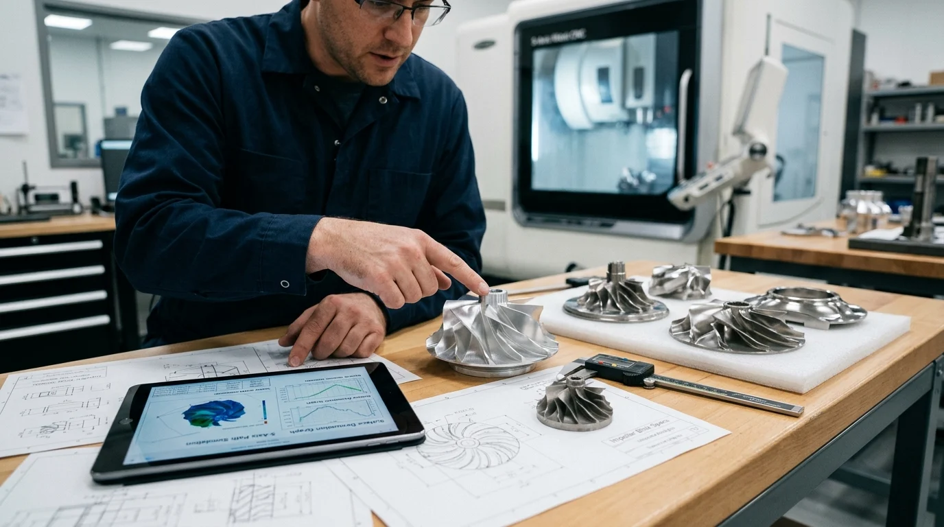
Aerospace parts that benefit most
The most profound benefits of 5-axis kinematics are realized in rotating engine components and critical structural elements. Turbine blades, blisks (bladed disks), and impellers feature aggressively twisted aerodynamic foils that cannot be accessed by fixed-angle spindles. Simultaneous 5-axis interpolation allows the cutting tool to maintain a continuous, optimal engagement angle relative to the airfoil surface, preventing gouging and maintaining uniform chip loads.
Beyond propulsion systems, large structural components such as wing ribs, fuselage bulkheads, and landing gear trunnions benefit immensely. These parts often feature deep pockets, undercuts, and intersecting compound angles designed to minimize weight without sacrificing strength. Machining these from high-strength alloys like Ti-6Al-4V or 7000-series aluminum requires the dynamic tool orientation that only a 5-axis platform can provide, allowing the use of shorter, more rigid tooling deep within component cavities.
Technical Advantages of 5-Axis Machining
The transition from conventional 3-axis milling to 5-axis simultaneous machining represents a fundamental shift in kinematic capability. By integrating two rotary axes (typically A and B, or A and C) with the standard linear X, Y, and Z axes, a 5-axis machining center can manipulate the tool or the workpiece into virtually any spatial orientation. This mechanical freedom translates into measurable technical advantages on the production floor.
Better accuracy and surface finish
One of the primary technical advantages of 5-axis machining is the ability to utilize significantly shorter cutting tools. Because the machine head or trunnion table can tilt to avoid collisions between the spindle housing and the workpiece, machinists do not need to rely on extended-reach end mills. Shorter tools possess exponentially higher dynamic stiffness, which drastically reduces tool deflection during heavy cuts.
This reduction in deflection directly translates to superior dimensional accuracy and exceptional surface finishes. In aerospace applications where surface anomalies can act as stress concentrators and initiate fatigue failure, achieving a surface roughness of Ra 0.4 µm or better without secondary hand-polishing is a critical advantage. The continuous tangential contact of the tool also eliminates the “stair-stepping” effect commonly seen in 3-axis contouring.
Fewer setups and improved tool access
Traditional machining of multifaceted aerospace parts often dictates three to six distinct fixturing setups. Each setup introduces a new zero point, creating an opportunity for tolerance stack-up. A 5-axis machine’s ability to articulate around the workpiece provides unparalleled tool access, allowing undercuts, side features, and compound-angle holes to be machined without human intervention.
Improved tool access also permits the use of specialized cutter geometries, such as barrel, lens, or taper-form end mills. By tilting the tool to match the curvature of an aerospace panel, a barrel cutter can achieve a massive step-over distance compared to a standard ball-nose end mill. This strategic tool presentation can reduce finishing cycle times by upwards of 70% while maintaining strict adherence to the required aerodynamic profiles.
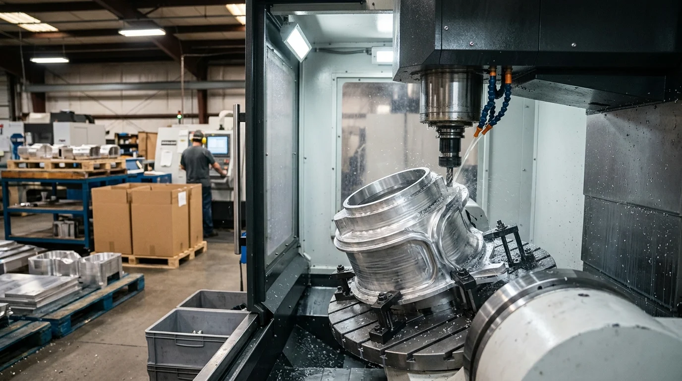
Higher efficiency and one-clamp machining
The “done-in-one” or “one-clamp machining” philosophy is fully realized through 5-axis technology. By machining five sides of a prismatic part in a single clamping operation, idle time is virtually eliminated. This continuous processing drastically improves overall equipment effectiveness (OEE) and spindle utilization rates, which often jump from a baseline of 40% in manual multi-setup environments to over 85% in automated 5-axis cells.
Higher efficiency is also driven by optimized cutting parameters. Because the tool vector is constantly adjusted to maintain ideal chip thickness and prevent the cutting speed at the tool tip from dropping to zero (a common issue with vertical ball-nose milling), tool life is significantly extended. In hard-to-machine materials like Inconel 718, this optimized engagement can reduce tool consumption costs by 30-50%.
5-Axis Machining vs Alternative Methods
While 5-axis simultaneous machining offers unparalleled capabilities, it is essential to contextualize its value against alternative manufacturing methods. Aerospace production engineers constantly weigh the merits of 3-axis milling, 3+2 positional machining, and near-net-shape processes like precision forging or investment casting against the capital and operational demands of full 5-axis platforms.
Key comparison criteria
Evaluating the correct machining methodology requires analyzing the interplay between part complexity, production volume, and geometric constraints. While 3-axis machines excel at flat, prismatic parts, they fail entirely at undercuts. Positional 3+2 machining bridges the gap by locking the rotary axes during the cut, offering better rigidity but lacking the capability to contour complex organic curves in a single continuous motion.
| Feature | 3-Axis | 3+2 Axis (Positional) | 5-Axis (Simultaneous) |
|---|---|---|---|
| Setup Count | High (3-6+) | Medium (2-4) | Low (1-2) |
| Tool Length Requirement | Long (Prone to deflection) | Moderate | Short (High rigidity) |
| Typical Surface Finish | Ra 1.6 – 3.2 µm | Ra 0.8 – 1.6 µm | Ra 0.2 – 0.4 µm |
| Complex Contouring | Impossible for undercuts | Limited to indexed angles | Fully supported |
Trade-offs in cost, programming, and inspection
The decision to adopt 5-axis machining involves significant trade-offs, primarily rooted in capital expenditure and programming complexity. A high-performance 5-axis machining center tailored for aerospace applications often requires an investment ranging from $500,000 to over $1.5 million, compared to $150,000 to $250,000 for a robust 3-axis vertical machining center. This upfront cost must be amortized over the machine’s lifecycle through increased throughput and reduced scrap.
Furthermore, programming simultaneous 5-axis toolpaths is exponentially more complex. It requires advanced Computer-Aided Manufacturing (CAM) software and highly skilled programmers to manage tool vectors, singularity points, and collision avoidance. Inspection protocols also escalate; verifying the complex, sweeping surfaces generated by a 5-axis machine demands advanced Coordinate Measuring Machines (CMM) capable of continuous scanning, adding to the overall quality assurance overhead.
Process Controls for Successful Implementation
Procuring a 5-axis machining center is only the first step in mastering aerospace complex surface processing. The physical hardware must be supported by a robust ecosystem of process controls. Without strict environmental, digital, and mechanical oversight, the inherent accuracy of the machine can be easily compromised by thermal drift, tool wear, or kinematic misalignment.
CAM, post-processing, and tooling
The success of 5-axis machining is heavily reliant on the digital twin and the CAM environment. Programmers must utilize simulation software to verify toolpaths, ensuring that the spindle, tool holder, and trunnion do not collide during complex multi-axis interpolations. Post-processors must be meticulously customized to translate the CAM data into the specific G-code dialect optimized for the machine’s CNC controller, managing feed rate smoothing and acceleration/deceleration profiles to prevent surface gouging.
Tooling selection and workholding are equally critical. High-speed 5-axis contouring demands exceptional balance and concentricity. Aerospace manufacturers typically standardize on shrink-fit or hydraulic tool holders that guarantee a total indicator runout (TIR) of less than 0.003 mm at the tool tip. Workholding must provide maximum clamping force with minimal physical interference, often utilizing zero-point clamping systems or dovetail fixtures that elevate the billet for full 5-sided spindle access.
Probing, calibration, and thermal compensation
To maintain aerospace tolerances, closed-loop process control via on-machine probing (OMP) is mandatory. Spindle-mounted probes are used to establish part datum points, measure critical features mid-cycle, and automatically update tool wear offsets in the CNC controller. This mitigates the risk of non-conformance before the part is ever removed from the fixture. Additionally, periodic kinematic calibration using a master calibration sphere ensures the rotary axes’ centerlines intersect precisely, correcting minor mechanical deviations.
Thermal stability is perhaps the most insidious variable in long-cycle aerospace machining. A temperature fluctuation of just a few degrees can cause cast iron machine frames and spindles to expand, shifting the tool center point by tens of microns. To combat this, advanced 5-axis centers employ comprehensive thermal compensation strategies, including chilled coolant routed through the spindle housing, ballscrews, and machine castings, strictly maintaining the structural temperature within ±0.5°C of the ambient environment.
How to Evaluate 5-Axis for Aerospace Production
Integrating 5-axis machining into an aerospace production facility requires a rigorous evaluation process. Decision-makers must align the machine’s specific kinematic and dynamic capabilities with the metallurgical properties of the components they intend to manufacture, while simultaneously constructing a resilient financial justification for the capital expenditure.
Machine selection criteria
Machine architecture dictates its application. Trunnion-style machines generally offer superior rigidity for heavy roughing of titanium, while swivel-head/rotary-table configurations are often preferred for massive structural components where the workpiece is too heavy to tilt dynamically. Spindle specifications must also be matched to the material: machining aluminum wing ribs demands high-speed spindles (20,000 to 30,000 RPM) to maximize feed rates, whereas cutting Inconel engine casings requires high-torque gear-driven or robust synchronous motor spindles capable of delivering over 1,000 Nm of torque at low RPMs.
| Aerospace Material | Typical Application | Spindle Requirement | Coolant Strategy |
|---|---|---|---|
| Aluminum Alloys (7075) | Wing ribs, bulkheads | High Speed (20,000+ RPM), Low Torque | High-volume flood, MQL |
| Titanium (Ti-6Al-4V) | Landing gear, engine mounts | High Torque (800-1,200 Nm), Low RPM | High-pressure through-spindle (1,000+ psi) |
| Inconel (718/625) | Turbine blades, exhaust | Ultra-High Torque, High Rigidity | Chilled high-pressure coolant |
Building the business case
Building the business case for a 5-axis platform requires calculating the total cost of ownership (TCO) against the projected operational savings. The analysis must quantify the reduction in fixture manufacturing, the elimination of manual setup labor, and the dramatic decrease in setup-induced scrap—which can account for up to 40% of waste in traditional multi-setup aerospace workflows.
When accounting for the increased material removal rates, consolidation of operations, and the premium commanded by complex, monolithic aerospace components, facilities often project a return on investment (ROI) within 24 to 36 months. Furthermore, possessing state-of-the-art 5-axis capabilities allows contract manufacturers to bid on advanced aerospace defense and commercial space contracts that strictly mandate one-clamp machining for geometric integrity, thereby opening new streams of high-margin revenue.
Key Takeaways
- The most important conclusions and rationale for Advantages of 5-Axis Machining Centers in Aerospace Complex Surface Processing
- Specs, compliance, and risk checks worth validating before you commit
- Practical next steps and caveats readers can apply immediately
Frequently Asked Questions
Why are 5-axis machining centers important for aerospace complex surfaces?
They machine twisted airfoils, deep pockets, and compound angles in one setup, helping meet tight aerospace tolerances while cutting lead time and reducing alignment errors.
Which aerospace parts benefit most from 5-axis machining?
Typical parts include turbine blades, blisks, impellers, wing ribs, bulkheads, and landing gear components made from titanium, aluminum, or superalloys.
How does 5-axis machining improve surface finish and accuracy?
By using shorter, stiffer tools and continuous tool tilting, it reduces deflection, avoids stair-stepping, and helps achieve fine finishes such as Ra 0.4 µm.
Can OTURN Machinery supply 5-axis solutions for aerospace manufacturers?
Yes. OTURN Machinery offers 5-axis machining centers and related CNC solutions, backed by group-factory resources, practical configurations, and overseas-oriented sales support.
How does 5-axis machining reduce production cost in aerospace?
It lowers setup count, shortens cycle time, improves tool access, and reduces rework, which is especially valuable when machining expensive materials like Ti-6Al-4V.
Post time: May-20-2026