


Introduction
Temperature changes during CNC machining can quietly distort both the machine and the workpiece, leading to dimensional drift, poor surface quality, and avoidable rework. In high-precision production, even small thermal shifts can undermine tolerance control and raise costs across an entire batch. This article explains five practical ways to reduce thermal deformation before it turns into a quality problem. You will learn where heat-related errors come from, how they affect machining stability, and which shop-floor adjustments can improve consistency, accuracy, and process reliability in daily CNC operations.
Why Thermal Deformation Matters in CNC Machining
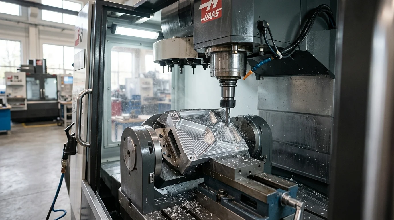
Thermal deformation remains one of the most pervasive challenges in high-precision CNC machining. As cutting tools engage workpieces, the conversion of mechanical energy into thermal energy causes localized and systemic expansion. Controlling this phenomenon is critical for maintaining rigid tolerances, ensuring part interchangeability, and maximizing overall equipment effectiveness (OEE).
Impact on dimensional accuracy and cost
Research indicates that thermally induced deviations can account for 40% to 70% of the total volumetric errors in a CNC machine tool. When machining parts to IT6 or IT7 tolerance grades, even a temperature fluctuation of a few degrees can push dimensions out of specification. Consequently, unchecked thermal expansion drives scrap rates up and necessitates costly manual rework. In high-precision batch runs, failing to account for thermal drift can increase total production costs by 15% to 25% due to wasted material and lost machining time.
Industries with the highest risk
The stakes are exceptionally high in sectors such as aerospace, medical device manufacturing, and semiconductor equipment production. Aerospace components, often machined from complex superalloys, require dimensional stabilities within ±0.005 mm over large spans. Medical implants demand exact geometric conformity to ensure biocompatibility and functional integration. In these high-risk industries, a failure to manage thermal profiles during the machining cycle directly jeopardizes regulatory compliance, component lifespan, and end-user safety.
Main Causes of Thermal Deformation
Understanding the root causes of thermal deformation requires a comprehensive examination of both the machining environment and the physical mechanics of material removal. Heat is an unavoidable byproduct of cutting, but its distribution and absorption dictate the severity of dimensional distortion.
Definition of thermal deformation in CNC machining
Thermal deformation in CNC machining refers to the physical expansion or contraction of the machine tool structure, the cutting tool, and the workpiece due to temperature variations. This behavior is governed by the coefficient of thermal expansion (CTE) of the specific materials involved. When a workpiece heats up during material removal, it expands; if it is machined to its final dimensions while in this expanded state, it will inevitably contract upon cooling, resulting in an undersized and non-compliant part.
Primary heat sources in the machining process
The primary heat sources in any machining setup are categorized as internal or external. Internally, the cutting zone is the most intense source, where the plastic deformation of the metal and the friction between the tool and the chip generate massive localized heat. Additionally, internal machine components such as spindle bearings rotating at 12,000 to 20,000 RPM, rapidly actuating ball screws, and hydraulic systems contribute significant thermal loads. If uncompensated, spindle temperatures alone can rise by 20°C to 40°C during continuous operation. Externally, ambient shop floor temperature fluctuations and direct sunlight can induce asymmetrical thermal gradients across the heavy machine casting.
How to evaluate thermal effects in production
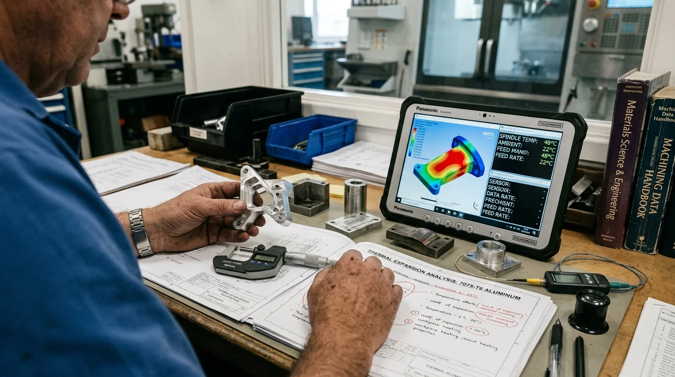
Evaluating these thermal effects in a production environment requires empirical measurement and real-time monitoring. Manufacturing engineers typically deploy surface thermocouples and infrared thermal imaging to map heat distribution across the workpiece and the machine structure. For precise volumetric compensation, laser interferometry is utilized to measure the thermal drift of the machine’s linear axes over extended periods, providing the necessary empirical data to update the machine’s kinematic models and offset parameters.
Practical Ways to Prevent Thermal Deformation
Mitigating thermal distortion requires a multi-layered approach that addresses the machine state, the cutting mechanics, and the physical handling of the workpiece. Implementing practical, standardized interventions can drastically reduce temperature-induced dimensional drift.
Machine warm-up and thermal stabilization
A fundamental preventative measure is establishing a rigorous machine warm-up and thermal stabilization protocol. Operating a cold machine immediately at high speeds introduces rapid, uneven expansion across the casting and drive systems. Best practices dictate running a spindle warm-up cycle at 50% of the maximum RPM and cycling all linear axes through their full travel for 15 to 30 minutes prior to cutting. This allows the spindle bearings, ball screws, and casting to reach a steady-state operating temperature, normalizing the thermal expansion before the first chip is made.
Tooling, cutting parameters, and coolant control
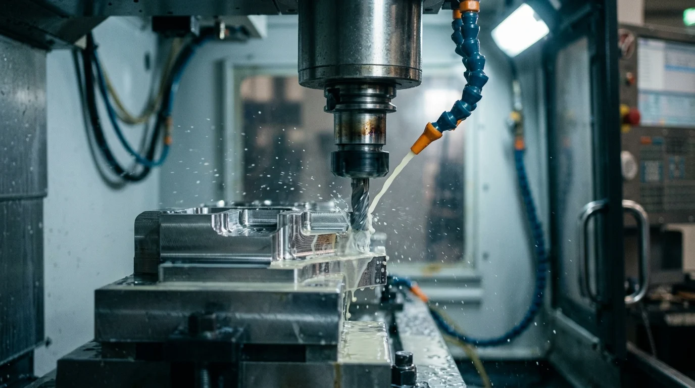
Tooling selection and cutting parameters heavily influence the ratio of heat transferred into the workpiece versus the chip. Utilizing sharp tools with positive rake angles reduces cutting forces and friction. Furthermore, aggressive feed rates combined with optimal surface speeds can ensure that the majority of the heat is carried away by the chip rather than absorbed by the part.
| Coolant Strategy | Heat Removal Efficacy | System Cost | Best Application |
|---|---|---|---|
| Standard Flood (20-50 psi) | Moderate | Low | General machining, low-heat materials |
| High-Pressure (1000+ psi) | Excellent | High | Deep hole drilling, titanium, Inconel |
| Minimum Quantity Lubrication (MQL) | Low (relies on chip heat transfer) | Medium | Aluminum, environmentally sensitive shops |
| Cryogenic (Liquid Nitrogen/CO2) | Superior | Very High | Hard-to-machine superalloys, aerospace |
Fixturing, machining sequence, and in-process measurement
Fixturing strategies must accommodate potential expansion without distorting the part. Over-constraining a workpiece can lead to bowing or warping as it heats up. Utilizing kinematic mounts or compliant clamping mechanisms allows for natural thermal expansion during heavy material removal. Furthermore, adjusting the machining sequence is vital. A standard expert practice is to separate roughing and finishing operations. Because roughing generates the most heat, machinists should leave 0.2 mm to 0.5 mm of stock material and allow the part to normalize to ambient temperature before executing the final finishing pass. In-process probing can then verify dimensions post-cooling and automatically update tool offsets.
Process Comparison and Implementation
Implementing effective thermal control is not a one-size-fits-all endeavor. The strategies deployed must be tailored to the specific metallurgical properties of the workpiece and seamlessly integrated into the operational realities of the shop floor.
Comparing materials and machining conditions
Different materials exhibit vastly different thermal behaviors under identical machining conditions. High thermal conductivity allows heat to dissipate quickly, while a high coefficient of thermal expansion means the material will grow significantly per degree of temperature rise.
| Material | CTE (µm/m·°C) | Thermal Conductivity (W/m·K) | Machining Thermal Risk Level |
|---|---|---|---|
| Aluminum (6061) | 23.6 | 167.0 | High (High expansion, but rapid cooling) |
| Carbon Steel (1045) | 11.5 | 49.8 | Medium (Moderate expansion and cooling) |
| Titanium (Ti-6Al-4V) | 8.6 | 6.7 | Very High (Low expansion, extreme heat retention) |
| Invar 36 | 1.2 | 10.1 | Low (Minimal expansion) |
Machinists must adapt their parameters based on these profiles. For instance, titanium requires aggressive high-pressure coolant to compensate for its inability to conduct heat away from the cutting zone, whereas aluminum requires careful measurement timing due to its rapid and significant dimensional changes.
Step-by-step implementation for process improvement
Process improvement should follow a systematic, step-by-step implementation phase. Step one involves establishing a baseline by machining a test artifact and measuring it both hot (immediately post-machining) and cold (after a 24-hour normalization period). Step two requires stabilizing the ambient environment, which often involves upgrading the facility’s HVAC system to maintain a strict shop floor temperature of 20°C ± 1°C. Step three is the integration of coolant temperature control and the optimization of CAM tool paths to distribute heat evenly. Finally, continuous verification through statistical process control (SPC) ensures that the implemented thermal management techniques remain effective over subsequent, long-term production runs.
How to Choose the Right Thermal Control Strategy
Selecting the optimal thermal control strategy requires a careful analysis of the production environment, the specific geometric tolerances required, and the available capital budget. Engineering and procurement teams must collaborate to find a balanced, cost-effective solution.
Balancing tolerance, cycle time, and equipment limits
The core conflict in thermal management lies between tight tolerances and cycle times. Allowing a workpiece to cool naturally between roughing and finishing passes guarantees higher accuracy but extends cycle times, thereby reducing overall throughput. If production schedules cannot accommodate cooling pauses, facilities must invest in active thermal management. This often involves integrating spindle chillers and temperature-controlled coolant systems capable of maintaining cutting fluids at a constant 20°C ± 0.5°C. While these systems require significant power and maintenance overhead, they allow for continuous, high-speed machining of tight-tolerance components without the penalty of thermal drift.
Decision guidance for engineering and procurement
Procurement decisions should be guided by a comprehensive total cost of ownership (TCO) analysis. For legacy equipment, retrofitting active chiller units or investing in high-pressure coolant delivery may provide a sufficient return on investment by significantly lowering scrap rates. However, for new acquisitions intended for sub-micron precision, engineering must specify machine tools equipped with absolute linear glass scales and advanced thermal compensation algorithms. These modern CNC controllers utilize strategically placed thermistors to dynamically adjust axis positions in real-time, effectively nullifying thermal expansion. The initial CapEx premium for these features—often 10% to 20% of the machine’s base price—is rapidly offset by the elimination of thermal-induced rework and the ability to run lights-out manufacturing reliably.
Key Takeaways
- The most important conclusions and rationale for CNC Machining
- Specs, compliance, and risk checks worth validating before you commit
- Practical next steps and caveats readers can apply immediately
Frequently Asked Questions
Why is thermal deformation a major issue in CNC machining?
Heat from cutting, spindle motion, and ambient changes can shift dimensions enough to cause IT6-IT7 parts to go out of tolerance, increasing scrap and rework.
How long should a CNC machine warm up before precision cutting?
A practical baseline is 15-30 minutes, with spindle warm-up at moderate RPM and full-axis travel cycling until machine temperature stabilizes.
Which OTURN machine types help reduce thermal deformation?
High-rigidity machining centers, turning centers, and 5-axis machines with stable structures, vibration absorption, and suitable coolant options help control heat-related drift.
What shop-floor steps can reduce thermal drift quickly?
Keep ambient temperature stable, avoid direct sunlight, use consistent coolant flow, monitor spindle heat, and avoid switching from idle to full-load cutting abruptly.
How can manufacturers verify thermal effects on CNC accuracy?
Use thermocouples or thermal imaging for heat mapping, then check axis drift with test cuts or laser measurement and adjust offsets based on stable operating conditions.
Post time: May-12-2026