


Why 5-Axis Machining Centers Matter in Aerospace
The shift toward these systems is heavily driven by stringent industry tolerances, which frequently mandate geometric dimensioning and tolerancing (GD&T) profiles within +/- 0.0001 inches (2.54 microns). By consolidating operations and minimizing part handling, 5-axis machining centers directly address the core vulnerabilities of aerospace production: cumulative setup errors, excessive fixture costs, and prolonged lead times.
Aerospace production demands driving adoption
The push for fuel efficiency and payload optimization has driven a massive increase in the use of lightweight, high-strength alloys and the integration of multiple sub-components into single, monolithic parts. This design philosophy drastically increases the “buy-to-fly” ratio—often exceeding 20:1 in raw material volume compared to the finished component weight. Machining away 95% of a titanium forging requires highly efficient material removal strategies that only multi-axis systems can sustain over long cycle times.
Furthermore, the aerospace supply chain is under intense pressure to accelerate production rates to clear massive commercial aircraft backlogs. Manufacturers are adopting 5-axis technology to compress manufacturing critical-path timelines. By reducing the number of distinct setups required to process a complex billet, production facilities can increase throughput without expanding their physical footprint or ballooning their labor overhead.
Complex parts that benefit most
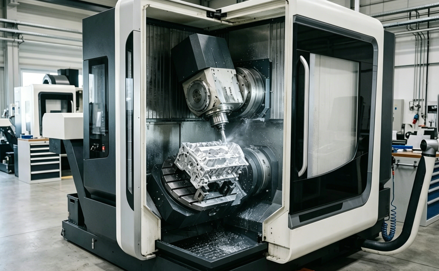
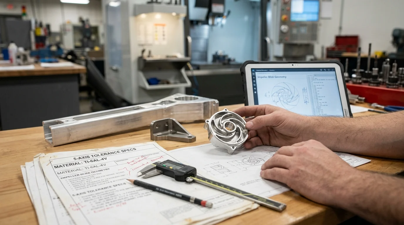
The geometric complexity of modern aerospace components dictates the use of simultaneous multi-axis interpolation. Turbine blades, impellers, and blisks (bladed disks) are prime examples; their aerodynamic, free-form surfaces feature undercuts and overlapping blade profiles that require constant dynamic reorientation of the cutting tool. Replacing a traditional multi-part rotor assembly with a monolithic blisk can reduce engine weight by up to 30%, but it mandates simultaneous 5-axis milling to access the tight channels between the airfoils.
Beyond propulsion systems, structural components such as fuselage bulkheads, landing gear struts, and wing ribs also reap massive benefits. These parts often feature deep pockets, thin walls, and complex draft angles. 5-axis machining allows the cutter to approach these features at optimal angles, maintaining rigidity and preventing the severe vibration or chatter that would otherwise compromise the structural integrity of thin-walled aerospace components.
What Defines 5-Axis Machining Centers for Aerospace
At the core of a 5-axis machining center is its ability to manipulate the X, Y, and Z linear axes alongside two rotary axes (typically A, B, or C). In the context of aerospace manufacturing, the specific configuration of these axes dictates the machine’s capability to handle varying part sizes, weights, and material hardness levels. High-performance spindles are paired with these kinematics, ranging from 30,000 RPM setups designed for rapid aluminum removal to high-torque, 4,000 RPM spindles engineered for cutting titanium and Inconel without stalling.
Machine architectures and kinematics
The architecture of a 5-axis machine fundamentally determines its application within an aerospace facility. The three primary configurations are trunnion-style (table-table), swivel head (head-head), and hybrid (head-table) designs. Trunnion machines tilt and rotate the workpiece, offering exceptional rigidity and precision for small, heavy components like jet engine impellers. Swivel head machines articulate the spindle itself, which is ideal for massive, heavy workpieces like wing spars that cannot be easily rotated.
| Architecture Type | Rotary Kinematics | Ideal Aerospace Application | Max Workpiece Size / Weight Limits |
|---|---|---|---|
| Trunnion (Table-Table) | A/C or B/C axes on the table | Blisks, impellers, small brackets | Small to medium (<1,500 mm / <2,000 kg) |
| Swivel Head (Head-Head) | A/B or A/C axes on the spindle | Wing ribs, large bulkheads, fuselage panels | Large to extra-large (>3,000 mm / >5,000 kg) |
| Hybrid (Head-Table) | One axis on head, one on table | Landing gear components, complex structural frames | Medium to large (Versatile hybrid limits) |
Simultaneous vs 3+2 machining
It is critical to distinguish between 3+2 positional machining and fully simultaneous 5-axis machining. In 3+2 machining, the rotary axes are used to orient the workpiece to a specific angle, locked in place, and then traditional 3-axis milling is executed. This is highly effective for processing multiple faces of a prismatic aerospace housing in a single setup.
Conversely, simultaneous 5-axis machining dynamically moves all five axes at once. This continuous contouring is required for the sweeping, aerodynamic curves of turbine blades. Simultaneous multi-axis execution can reduce cycle times on complex contoured surfaces by 25% to 40% compared to stepping down a surface with 3-axis toolpaths, as it utilizes the side of the cutting tool rather than relying on tiny step-overs with a ball-nose endmill.
Setup reduction compared with 3-axis machining
One of the most quantifiable metrics of 5-axis adoption is the drastic reduction in setup times. A complex aerospace valve body might require five or six distinct setups on a traditional 3-axis vertical machining center. Each setup demands custom fixturing, manual loading, dialing in, and probing—introducing stacked tolerance errors at every stage.
Transitioning that same component to a 5-axis machining center typically reduces the operation to just one or two setups (often referred to as “Done-in-One” or “Op 10 / Op 20″ processing). This consolidation not only strips out hours of non-value-added setup time but can also reduce custom fixture engineering and manufacturing costs by up to 60%, directly improving the profitability of low-volume, high-mix aerospace contracts.
Key Technical Advantages in Aerospace Machining
The technical superiority of 5-axis machining centers extends far beyond simple geometric capability; it fundamentally alters the physics of the cutting process. By maintaining optimal tool engagement and maximizing rigidity, aerospace manufacturers can achieve tighter tolerances, superior surface finishes, and significantly higher material removal rates (MRR). These technical advantages are essential for meeting the rigorous specifications of flight-critical hardware.
Accuracy and surface finish benefits
Aerospace components require pristine surface finishes to prevent micro-fractures and fatigue failures under cyclical stress. 5-axis simultaneous machining allows the tool to maintain a constant chip load and an ideal engagement angle relative to the part surface. By using the flank of the tool (flank milling) rather than the tip, manufacturers can achieve surface roughness (Ra) values down to 0.4 µm (16 µin) straight off the machine.
This level of precision effectively eliminates the need for manual polishing or secondary benchwork. Hand polishing is not only time-consuming but also introduces human error that can inadvertently alter the aerodynamic profile of a blade, leading to scrapped parts. The continuous toolpath control of a 5-axis machine ensures absolute repeatability across production batches.
Tool access, shorter tools, and cycle time gains
On a standard 3-axis machine, reaching the bottom of a deep cavity requires exceptionally long tools. Extended tool overhang dramatically reduces system rigidity, leading to tool deflection, chatter, and poor dimensional accuracy. 5-axis kinematics solve this by tilting the tool or the part, allowing the spindle housing to drop closer to the workpiece.
By reducing the tool’s length-to-diameter (L/D) ratio from a standard 10:1 down to 3:1, the rigidity of the cutting tool increases by a factor of 27 (since deflection is proportional to the cube of the length). This massive gain in stiffness allows programmers to push feed rates higher and take deeper depths of cut without risking tool breakage, resulting in cycle time reductions of 30% or more on deep-pocketed structural parts.
Material-specific benefits for titanium, aluminum, and composite
s
Different aerospace alloys demand highly specific machining strategies. For structural aluminum (e.g., 7075-T6), the goal is maximum MRR. A 5-axis machine equipped with a high-speed spindle can exceed a material removal rate of 500 cubic inches per minute in aluminum, utilizing dynamic tool tilting to plow through deep pockets rapidly while maintaining thin-wall stability.
In contrast, machining titanium (Ti-6Al-4V) or heat-resistant superalloys (HRSA) like Inconel requires immense torque and rigidity to combat work hardening and heat generation. 5-axis machines benefit these materials by allowing shorter, stiffer tools that limit deflection to under 0.002 inches, which is critical for tool life. Furthermore, carbon fiber reinforced polymers (CFRP) benefit from 5-axis routing, where the tool angle is continuously optimized to slice cleanly through the fibers, preventing delamination and fraying along complex aerostructure trim lines.
Implementation Factors and Process Control
Acquiring a 5-axis machining center is only the first step; unlocking its full potential requires a robust, integrated manufacturing ecosystem. The leap from 3-axis to 5-axis processing introduces significant complexities in programming, collision avoidance, and quality verification. Aerospace facilities must implement strict process controls to ensure that the theoretical capabilities of the machine translate into compliant, flight-ready hardware.
CAM programming and workflow requirements
The mathematics involved in simultaneous 5-axis toolpaths surpass human calculation, necessitating advanced Computer-Aided Manufacturing (CAM) software such as Siemens NX, Mastercam, or hyperMILL. Generating these toolpaths requires programmers to manage not just the tool tip, but the entire tool vector and spindle housing to prevent catastrophic collisions.
Consequently, the workflow must incorporate digital twin technology. Machining simulation software (like VERICUT) is mandatory in aerospace to run the G-code through a virtual machine model before actual chips are made. This software ecosystem upgrade is a significant investment, often adding $20,000 to $50,000 per machine in post-processors, simulation licenses, and specialized programmer training.
Quality, compliance, and capability control
Aerospace manufacturing is governed by strict quality management systems, notably AS9100D. 5-axis machines support compliance by integrating on-machine probing systems (such as Renishaw or Blum). These probes verify part location before machining, monitor tool wear during the cycle, and perform in-process dimensional verification, ensuring that the part remains within the required 10-micron volumetric accuracy.
To maintain this capability, machines undergo regular ISO 230-2 calibration and volumetric error compensation using laser trackers or ballbar systems. Tool Center Point Control (TCPC) and dynamic rotary tracking algorithms within the CNC control (like Heidenhain TNC 640 or FANUC 31i) continuously calculate and compensate for microscopic thermal drift and kinematic pivot errors in real-time.
Cost, complexity, and operational trade-offs
The transition to 5-axis machining involves distinct operational trade-offs. While the per-part cycle time and setup costs decrease, the initial capital expenditure and programming overhead increase substantially. A comprehensive cost-benefit analysis is required to justify the investment.
| Metric | Traditional 3-Axis VMC | Simultaneous 5-Axis Machining Center |
|---|---|---|
| Capital Investment | $80,000 – $180,000 | $350,000 – $1,200,000+ |
| Typical Setups per Complex Part | 4 to 7 setups | 1 to 2 setups |
| Fixture Engineering Cost | High (requires multiple custom jigs) | Low (utilizes standard zero-point systems) |
| Programming & Verification Time | Low to Moderate | High (requires intensive CAM and simulation) |
| Operator Skill Requirement | Moderate | Expert / Highly trained |
How to Decide When to Invest in 5-Axis Capability
Determining the right moment to integrate 5-axis machining into an aerospace supply chain requires balancing capital risk against strategic capability. Facilities must analyze their current bottlenecks, projected contract volumes, and the technical demands of upcoming aerospace programs. A typical return on investment (ROI) timeline for a 5-axis cell is 18 to 36 months, provided the facility can maintain a machine utilization rate of at least 70%.
Build vs outsource decision factors
The decision to build internal 5-axis capability versus outsourcing to specialized contract manufacturers hinges on intellectual property, volume thresholds, and supply chain resilience. If an OEM or Tier 1 supplier processes a high volume of proprietary monolithic components, bringing 5-axis capability in-house protects sensitive IP and eliminates the logistical delays of moving parts between external vendors.
Conversely, smaller shops facing sporadic, low-volume orders for complex geometries may find the $500,000+ capital expenditure mathematically unjustifiable.
Key Takeaways
- The most important conclusions and rationale for 5-Axis Machining Centers
- Specs, compliance, and risk checks worth validating before you commit
- Practical next steps and caveats readers can apply immediately
Frequently Asked Questions
Why are 5-axis machining centers essential for aerospace parts?
They machine complex surfaces, undercuts, and thin walls in fewer setups, which improves accuracy, shortens lead time, and reduces cumulative error on aerospace components.
Which aerospace parts benefit most from 5-axis machining?
Blisks, impellers, turbine blades, wing ribs, bulkheads, and landing gear parts benefit most because they combine free-form surfaces, deep pockets, and tight tolerance requirements.
How do 5-axis machines reduce aerospace production costs?
They cut fixture changes, handling time, and secondary operations. Fewer setups also lower scrap risk and help manufacturers achieve faster ROI on complex metal parts.
What 5-axis machine types does OTURN Machinery offer for different aerospace jobs?
OTURN supplies 5-axis machining centers within a broader CNC portfolio, including rigid, high-speed, heavy-duty, and linear-guideway variants for different aerospace materials and part sizes.
How do I choose between trunnion and swivel-head 5-axis machines?
Choose trunnion designs for smaller, high-precision parts like impellers; choose swivel-head machines for large, heavy structures such as wing spars or bulkheads that are difficult to rotate.
Post time: May-07-2026