


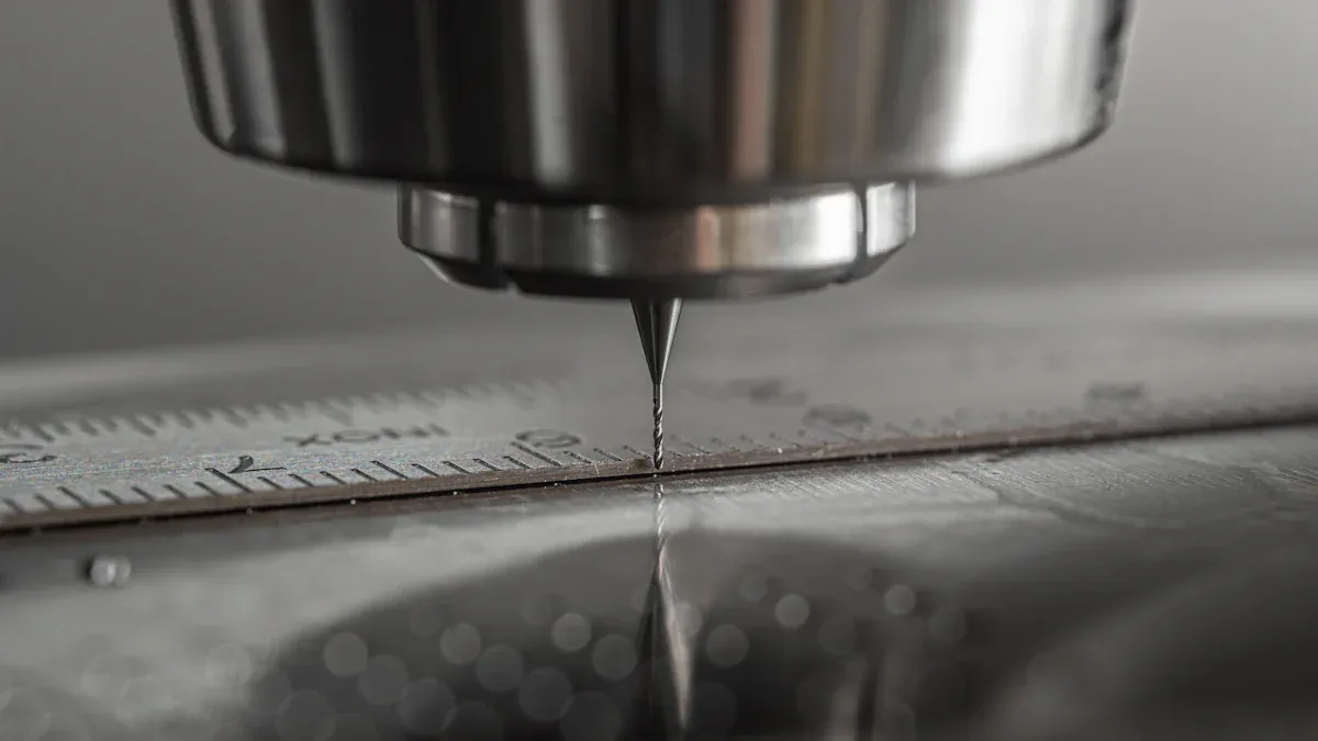
Precision remains paramount in modern manufacturing, especially for CNC Turning Center operations. Machining accuracy directly correlates with the quality of industrial metal parts produced. For example, precise valve machining relies heavily on this accuracy. Inaccurate components increase manufacturing costs and reduce operational efficiency significantly. A robust CNC Control System is crucial for maintaining this precision. Understanding how to improve CNC lathe precision thus becomes a critical factor for achieving success and ensuring product integrity.
Key Takeaways
- Precision in CNC turning is very important. It makes sure industrial metal parts are high quality. Good accuracy helps avoid mistakes and saves money.
- Many things affect how accurate a CNC machine is. These include how well the spindle works, the straightness of the guideways, and how the tool turret moves. Keeping these parts in good shape helps the machine work better.
- Machine stiffness and controlling vibrations are key. A strong machine does not shake much when cutting. This helps make parts more accurate and smooth. Using good tools and proper settings also reduces shaking.
- Outside factors like temperature changes and how parts are held also matter. Stable temperatures stop machine parts from changing size. Holding the workpiece firmly stops it from moving during cutting. This helps keep parts accurate.
- Regular care and checking the machine’s settings are a must. This includes daily checks and bigger yearly checks. Good maintenance keeps the machine working well and making accurate parts over time.
Geometric and Mechanical Factors in CNC Turning Center Accuracy

Spindle Performance and Alignment
The spindle forms the heart of any CNC Turning Center, directly influencing machining accuracy. Its performance and alignment are critical. Spindle runout, a deviation from the ideal rotational axis, significantly compromises precision. Several factors contribute to spindle runout. For instance, chuck issues often cause problems. An incorrect chuck size leads to misalignment between the chuck and spindle taper. Worn or damaged chuck components, such as jaws or internal mechanisms, result in insecure gripping. Tool issues also play a role. Tool wear makes tools less concentric, while tool damage, like chips or nicks, causes uneven cutting. Improper tool installation, with insufficient contact between the tool and tool holder taper, also contributes. Spindle issues themselves are major culprits. Worn spindle bearings increase play, and spindle misalignment affects the shaft or internal components. Contamination in the taper, such as metal chips, prevents proper toolholder seating, causing rocking motion.
Thermal expansion also impacts spindle accuracy. High spindle speeds generate excessive friction and heat. This heat causes thermal expansion of the material, tool deformation, and workpiece warping. Even microscopic dimensional changes compromise tight tolerances. For example, continuous operation at 9000 r/min for 2.5 hours can cause a sharp temperature rise of about 7℃, leading to significant deformations in the Y and Z directions. Advanced cooling systems, including liquid and air cooling, regulate temperature and ensure thermal stability, maintaining precision during extended operations.
Guideway Precision and Perpendicularity
Guideways provide the precise motion for the machine’s axes. Their precision and perpendicularity are fundamental for accurate part production. Any deviation in guideway straightness or perpendicularity directly translates to dimensional errors on the workpiece. Over time, guideways can experience wear. Uneven guideway wear or poor lubrication leads to ‘stick-slip’ motion and inconsistent friction. This causes the servo system to lose direction at the final stage of movement, directly impacting the machine’s repeatability and positioning accuracy. A decline in machining accuracy is one of the most obvious signs of worn guideways. Finished parts may no longer meet specified tolerances, and parts that should be consistent may show inconsistencies. Operators also observe unexpected marks or roughness and a deteriorating surface finish.
Turret Indexing and Repeatability
The turret holds multiple tools and rapidly indexes them into position. Its indexing precision and repeatability are vital for consistent part quality. Each time the turret rotates to present a new tool, it must return to the exact same position relative to the workpiece. Any error in indexing introduces positional inaccuracies, affecting subsequent machining operations. Poor repeatability means the tool position varies slightly with each index, leading to dimensional inconsistencies across parts. This factor becomes especially critical in multi-tool operations where tight tolerances are necessary.
Machine Rigidity and Vibration Control
Machine rigidity forms a cornerstone of precision machining. A rigid machine structure resists deformation under cutting forces, which directly translates to higher accuracy and better surface finishes. Conversely, insufficient rigidity leads to vibrations, significantly degrading part quality.
Vibrations in machining operations originate from various sources. Inherent machine vibrations arise from the machinery itself. Spindle rotation, especially if misaligned or imbalanced, generates significant vibration. The interaction between the tool and workpiece also creates resistance during cutting, causing the tool to chatter, particularly with hard materials or complex paths. Worn tools further decrease stability and increase vibration. External vibrations also impact machine performance. These include environmental factors, such as vibrations from nearby machinery or building infrastructure, and operational impacts like shockwaves from other facility operations. Low-frequency vibrations, often dominated by the workpiece system, can lead to self-excited vibration due to periodic changes in cutting force. These conditions include friction between chips and the tool, differences in metal hardening, and periodic changes in the tool’s geometric angle during vibration.
Effective strategies mitigate machine tool vibration and improve machining accuracy. Manufacturers ensure robust and balanced tool holders and use appropriate fixtures for the workpiece to minimize movement. They implement damping techniques, utilizing materials or devices like viscoelastic or tuned mass dampers within the machine or tooling system to absorb vibrations. Optimizing the tool path and machining strategy helps avoid sudden changes in direction; smooth, continuous tool paths reduce vibration. High-performance tooling systems, with features like variable helix angles or harmonic dampening, are designed to reduce chatter. Regular maintenance and calibration of machine components, such as bearings and guides, ensure structural integrity and sustained rigidity. Minimizing tool overhang and using balanced tool assemblies also enhance rigidity. Optimizing cutting parameters like spindle speed, feed rate, and depth of cut further reduces vibrations.
Environmental and Operational Influences on CNC Turning Center Precision
Thermal Stability and Deformation Management
Temperature fluctuations significantly impact machining accuracy. Machines generate heat during operation, causing thermal expansion of components. This expansion leads to dimensional changes and positional errors. Effective thermal management is therefore critical. Manufacturers employ various strategies to mitigate these effects. One common method involves an integrated modeling approach for ANN-based real-time thermal error compensation. Researchers like Ouafi, Guillot, and Barka have explored this technique for real-time adjustments on a CNC turning center, ensuring consistent precision despite temperature shifts. Maintaining a stable ambient temperature in the machining environment also helps prevent thermal deformation.
Workpiece Clamping and Fixturing Integrity
Proper workpiece clamping and fixturing are fundamental for achieving high precision. The clamping system must securely hold the workpiece without inducing stress or deformation. Insufficient clamping force can lead to workpieces shifting during machining, which directly results in poor dimensional control. Variations in clamping force can cause mismatched seams or joints, where machined components do not align correctly. Furthermore, inadequate support or clamping during machining can lead to internal stress and distortion, causing the part to warp or deform. Operators must ensure the fixture design provides rigid support and distributes clamping forces evenly across the workpiece surface.
Cutting Fluid Application and Effectiveness
Cutting fluid plays a vital role in managing heat, lubricating the cutting zone, and evacuating chips. Its effective application directly influences machining accuracy and surface finish. The flow velocity of the cutting fluid directly affects the kinetic energy of chips during chip evacuation. A higher flow velocity can effectively enhance the drag force of cutting fluid on chips, promoting the rapid discharge of chips from the machining area. The cutting fluid flows along the outer wall of the tool during the process of entering the chip evacuation channel, and the tool geometry directly affects the movement path of the cutting fluid. Especially at the inlet of the tool chip evacuation channel, the flow state of the cutting fluid is non-uniform with large velocity fluctuations, which can easily lead to chip accumulation.
Consider these best practices for optimal cutting fluid use:
- Use high-pressure or through-spindle coolant systems for deep or high-speed cuts.
- Maintain stable coolant temperature to prevent thermal shock.
- Adjust flow rate to provide even coverage across the cutting zone.
| Main Goal | Recommended Cutting Fluid |
|---|---|
| High-speed machining | Synthetic or semi-synthetic |
| Heavy-duty cutting (steel, titanium) | Straight oils or emulsions |
| Precision machining | Water-soluble fluids |
| Chip evacuation | High-pressure synthetic fluids |
| Environmental concerns | Vegetable-based oils |
Maintenance and Calibration for Sustained Accuracy
Sustaining high accuracy in machining operations requires consistent maintenance and calibration. Inadequate servicing leads to a significant loss of precision. This results in defective parts and wasted materials, especially critical for industries with tight tolerances. For instance, an uncleaned CNC router can experience up to a 10% reduction in accuracy. Dust, debris, and contaminants affect moving parts, increasing wear and tear. Neglecting regular inspection, re-oiling, and setting causes components like ball screws, linear guides, and precision bearings to fall out of tolerance. This compromises machining accuracy.
To counteract this degradation, regular calibration becomes essential. Calibration intervals depend on several factors. These include manufacturer’s recommendations, frequency of use, environmental conditions, and the tool’s calibration history. While no universal standard exists, experts suggest calibrating CNC tools every 3-6 months. This frequency can vary based on specific usage and environmental factors.
A structured approach to calibration includes daily, monthly or quarterly, and annual checks.
- Daily Checks: Operators should check basic functions like spindle rotation, tool movement, and coolant flow. This helps identify early issues.
- Monthly or Quarterly Calibration: More comprehensive procedures, such as spindle runout measurement, tool post alignment, and linear axes positioning accuracy checks, should occur monthly or quarterly.
- Annual Calibration: A qualified technician performs a full-scale calibration of all key components. They use specialized equipment for this annual check.
This systematic approach ensures sustained accuracy for the CNC Turning Center.
Tooling and Material Considerations for CNC Turning Center Accuracy
Tool Wear and Breakage Impact
Tool wear significantly affects machining accuracy. Progressive tool wear directly influences the dimensional accuracy of machined components. Adhesion wear, caused by friction and high temperatures, impacts the workpiece’s dimensional accuracy. This occurs when chips bond with the tool face. As tool wear progresses, the accuracy of produced parts decreases. This can lead to parts going out of specification. Such parts may require scrapping or reworking. Multiple types of wear occurring simultaneously can exacerbate this problem.
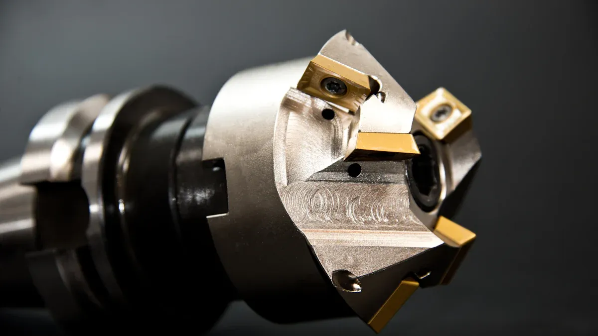
Tool Holder Rigidity and Runout
The tool holder’s precision directly influences runout, vibration, and tool wear. Collet-style holders are popular for accuracy and versatility. However, they are not immune to runout and uneven wear. The impact of runout on these holders increases with a higher length-to-diameter ratio and greater mass as the tool spins. Significant tool holder runout introduces considerable vibration. This degrades surface finish and can lead to cutter breakage. Smaller cutters are particularly susceptible to runout. For instance, a thousandth of an inch of runout is substantial for a 1/8″ cutter. It causes erratic movement during the cutting process. For high-precision applications, manufacturers favor shrink-fit and hydraulic holders. These achieve very low runout, typically ≤2–3 μm. This promotes smoother cutting and superior surface finishes. Miller states, “Runout accuracy is a very important consideration.” He adds that low runout leads to better part quality, improved cutting tool life, greater consistency, longer run times, and reduced tool breakage. Runout can also influence cutting force, potentially causing vibration and hindering machining accuracy.
Workpiece Material Properties and Machinability
Workpiece material properties greatly influence machining outcomes.
- Harder materials, like metals, generally lead to more significant tool wear. This necessitates using harder, more wear-resistant tool materials.
- Softer materials, such as plastics, typically result in less tool wear. However, proper tool selection and design remain critical for high-quality surface finishes.
- Metals can generally hold tighter tolerances and precision. They have more stable and consistent properties.
- Plastics may exhibit more variability in dimensions and properties. This can affect achievable tolerances. They can also be prone to burring or melting if not machined properly.
- Materials with poor machinability, often associated with higher hardness, cause rapid tool wear. This leads to frequent tool replacement and increased production costs.
- Achieving a smooth and precise surface finish is an essential aspect of machinability. Materials that tend to produce rough or irregular surfaces may require more post-processing.
- Work hardening can occur in certain materials during machining. This makes them more challenging to cut as the process progresses. It increases tool wear and reduces efficiency.
Optimized Cutting Parameters and Strategies
Optimizing cutting parameters and strategies significantly influences machining accuracy and efficiency. Manufacturers must carefully select cutting speeds, feed rates, and depths of cut to achieve desired part quality. Harder materials require lower cutting speeds to prevent excessive tool wear, while softer materials can handle higher speeds. Regularly inspecting cutting tools for wear prevents degradation of surface finish and accuracy. Controlling chip thickness by optimizing the feed rate ensures efficient material removal without overloading the tool. Balancing spindle speed with tool diameter helps avoid vibrations and improves cutting performance. Higher depths of cut necessitate slower feed rates to prevent tool overload and poor surface quality. Machine operators maintain machine stability by adjusting feed and cutting parameters based on the CNC machine’s capability. They always refer to tool manufacturer guidelines for ideal speeds and feeds for different tools and materials.
Several factors influence the selection of optimal cutting parameters. The workpiece material’s hardness significantly affects the appropriate cutting speed. The type, material composition, and geometry of the cutting tool also influence recommended cutting speeds; for instance, carbide tools allow for higher cutting speeds than high-speed steel tools. Chip load determines the material removal per tooth and influences the overall load the machine can manage. Optimizing chip load balances the material removal rate with machine efficiency. The available machine power dictates feasible feed rates and cutting speeds. A sharper cutter generally operates at higher feed rates and speeds. The tool’s cost can influence the acceptable level of wear and thus the chosen cutting parameters. For high-volume production, parameters might be optimized for productivity, potentially at the expense of tool life, whereas for low-volume, tool life might be prioritized.
Experiments on hardened AISI 4140 steel with coated carbide cutting tools showed that feed rate has the most significant effect on surface roughness. Interactions between feed rate-cutting speed and depth of cut-cutting speed were also important for minimizing surface roughness. Similarly, the application of Taguchi and response surface methodologies helped minimize geometric error in surface grinding by selecting optimum grinding conditions. Predictive models for surface roughness and tool wear in finish hard turning indicated that decreasing feed rate improved surface roughness but slightly accelerated tool wear. Increasing cutting speed significantly increased tool wear but resulted in better surface roughness. Increased workpiece hardness led to better surface roughness but higher tool wear. Investigations into finish hard turning of MDN250 steel revealed that cutting forces and surface roughness did not significantly vary with experimental cutting speed within a specific range.
Control System and Programming Precision in CNC Turning Centers
CNC Controller Resolution and Interpolation
The CNC controller acts as the machine’s brain. Its resolution determines the smallest movement increment the machine can make. A higher resolution allows for finer control and greater precision in machining operations. Interpolation refers to the controller’s ability to generate smooth, continuous tool paths between programmed points. Accurate interpolation ensures the tool follows the intended geometry precisely, preventing jagged edges or deviations from the design. Poor resolution or interpolation leads to dimensional inaccuracies and a compromised surface finish on the workpiece.
Feedback System Accuracy and Reliability
Feedback systems continuously monitor the machine’s position and speed. They send this data back to the controller. This allows the controller to make real-time adjustments. Accurate and reliable feedback is crucial for maintaining precise control over tool movements. Rotary encoders are often used; they are cost-effective and perform well for shorter axes. Linear scales offer superior accuracy over longer distances. These are more expensive but essential for high-tolerance applications, especially in machines like CNC lathes. These systems ensure the machine executes programmed movements exactly as intended, correcting for any minor deviations.
G-Code and M-Code Programming Integrity
G-code and M-code form the language of CNC machines. Programmers write these codes to instruct the machine on every movement and function. Errors in programming directly translate to machining inaccuracies. Mistakes with G-codes are common. They lead to poor results and risk damage to holders, products, cutters, and the machine. This happens if programmers do not properly program the correct cutters and cutting sequence. Ignoring M-codes also causes issues. For example, a clamp might not engage, stressing the rotary axis. This occurs due to a lack of thorough understanding of M-codes for clamping, coolant, or spindle control. Incorrect G-code commands or tool offsets cause unexpected tool movements. Incorrect tool paths or insufficient clearance lead to tool crashes. Syntax issues, such as missing symbols or invalid commands, can halt the program. These programming errors severely impact part quality and machine safety.
Offset Management and Compensation Techniques
Effective offset management and compensation techniques are crucial for achieving high precision in machining. These methods account for variations that occur during the manufacturing process. Tool offset compensation addresses the difference between assumed and actual tool lengths. This function allows for simultaneous adjustments along both the X and Z axes in a CNC lathe system. It handles two main types of offsets: tool geometric offset, which arises from differences in tool shapes and installation positions, and tool wear offset, which corrects for the gradual wear of the tool tip.
Operators apply tool offset through a tool setting operation. This process adjusts the tool’s position to align with an ideal reference point. It typically involves machining the end face to record the Z-direction mechanical coordinate. Then, operators machine the outer circle to record the X-direction mechanical coordinate and measure the workpiece diameter. They input these X and Z values into the tool geometry offset memory. The primary goal of this compensation is to align the workpiece coordinate system’s origin with the machine tool’s origin. This effectively corrects machining errors from inaccurate tool setting or tool wear. For example, if an outer diameter is 0.2mm larger than required, reducing the X value in the tool offset memory by 0.2 and re-machining with the same tool and program can correct the error.
Wear offset is a specific type of tool offset. Manufacturers utilize it to adjust the leading tool offset after tool wear occurs, especially during long machining runs. This approach helps maintain consistency with base values and provides a safeguard for backtracking if issues arise.
Tool nose arc radius compensation is another vital method used in CNC turning centers. It ensures workpiece contour accuracy, particularly when the turning tool’s tip is ground into an arc due to wear or finishing requirements. In these situations, the tool position is considered the center of this arc. To maintain the desired workpiece contour, the movement path of the tool nose arc’s center must offset from the workpiece contour by a radius value. This compensation is critical because tool tips are not ideal points but rather arcs. Ignoring this fact leads to machining errors. Without this compensation, issues can arise, such as residual errors at the center of end faces or clear corners of steps. It can also impact the size of large and small ends when machining conical surfaces, enlarging outer cones and shrinking inner cones. Furthermore, it distorts the roundness and radius of arcs, making convex arcs smaller and concave arcs larger.
The Strategic Importance of Understanding CNC Turning Center Accuracy Factors
Minimizing Scrap and Rework Costs
Understanding and maintaining high accuracy in machining operations directly translates to significant cost savings. Inaccurate parts often become scrap, meaning manufacturers must discard them. This results in wasted raw materials, energy, and labor. Alternatively, inaccurate parts may require rework, which involves additional machining, inspection, and labor. Both scrap and rework increase production costs and extend manufacturing timelines. Precision machining reduces the likelihood of producing defective components. This minimizes material waste and decreases the need for costly secondary operations. Companies save money by getting the part right the first time.
Improving Production Lead Times and Throughput
High accuracy significantly improves production lead times and overall throughput. When machines consistently produce parts within specifications, manufacturers avoid delays caused by rework or quality control issues. Combining CNC turning and precision milling services under one roof reduces lead time and improves tolerances. This integration creates a seamless flow from raw material to finished part. For example, a turned shaft with milled keyways can move between machines without leaving the shop floor. This integrated approach leads to better quality control, faster project turnaround, and more accurate assemblies. More accurate cutting prevents the need to redo jobs, saving time on projects. Automating aspects of machining, such as setting tools, reduces the time required for each task. More efficient operations, resulting from improved accuracy, reduce the waiting time for completed projects. Tool presetters can measure tool placement accuracy in under a minute. In contrast, a machinist using a touch probe takes over an hour to set 15 tools for a project. This highlights the efficiency gains from advanced accuracy tools. A tool-making company that had not updated equipment since 1987 saw significant improvements after upgrading software and hardware. New equipment could predict tool movements by looking forward up to 1,000 lines of point data in the program. This enhanced predictive capability made machining more efficient and accurate, thereby reducing turnaround times.
Enhancing Product Performance and Reliability
Machining accuracy directly correlates with the functional performance and lifespan of manufactured components. Accurate machining ensures that parts precisely match design specifications. This allows them to fit correctly and perform their intended functions. Adherence to specifications is crucial for component longevity and overall product quality. Conversely, inaccuracies can lead to part failures, safety hazards, and diminished product quality. Components may not function as designed or may fail prematurely under operational conditions. This is particularly critical in industries like aerospace, medical, and automotive, where precise fit and function are paramount for safety and reliability. Accurately machined parts fit together without the need for adjustments, streamlining the assembly process. This reduces labor costs and prevents production delays. Accurate prototypes enable engineers to thoroughly test a design’s form, fit, and function. This ensures the prototype’s performance closely mirrors the final product, which is vital for validation before mass production. High accuracy ensures components meet strict industry regulations and design blueprints. This is essential for functionality, longevity, and overall product quality, reducing defects and enhancing customer satisfaction.
Boosting Customer Satisfaction and Market Reputation
High machining accuracy directly enhances customer satisfaction and strengthens a company’s market reputation. When products consistently meet or exceed quality expectations, customers develop trust in the brand. This trust translates into repeat business and positive word-of-mouth referrals. Studies show that increasing customer retention rates by just 5% can elevate profits by 25% to 95%. This highlights the significant financial benefits of maintaining high product quality.
Manufacturers also face substantial costs from inefficiencies. Outdated systems, for example, cost manufacturers approximately USD $25.8 billion annually in wasted managerial time. By enhancing quality systems, companies can reduce these losses and maintain profitability. They also lower costs associated with returns, repairs, and warranty claims.
Improved product and service quality leads to faster market acceptance. It also results in fewer customer complaints and a stronger brand reputation. Enhanced product quality reduces rework, minimizes recalls, and lowers rejection rates. This brings significant cost savings and more predictable production timelines. Quality improvements foster trust from stakeholders, regulators, customers, and investors. A satisfied customer is more likely to return, recommend the product, and show loyalty. This influences long-term revenue and brand reputation.
Standardizing processes and procedures delivers consistent outcomes. This improves customer retention and satisfaction. Complaint management procedures within a Quality Management System (QMS) enable quick resolution and documentation of problems. This reinforces accountability and reliability. Systematic collection of customer feedback helps prevent repeat issues. Structured quality records provide traceability. This aids in identifying recurring issues and taking timely corrective actions. Standard operating procedures ensure consistent product or service quality across teams and timeframes. Defined responsibilities and approval workflows reduce delays and miscommunication. This enhances the customer experience. The advantage of enhanced satisfaction is stronger trust and loyalty. Retention also reduces the cost of acquiring new customers. Indirect advantages include increased referrals and more favorable reviews.
Comprehensive knowledge of CNC Turning Center accuracy factors plays an indispensable role in modern manufacturing. This understanding allows companies to achieve superior precision. It provides a significant competitive advantage. Manufacturers continuously pursue precision. They leverage emerging technologies like AI-driven quality control and digital twin technology. Advanced CNC software also enhances this pursuit. Proactive management and real-time monitoring serve as cornerstones. These practices ensure sustained quality and operational excellence.
FAQ
How does spindle runout affect machining accuracy?
Spindle runout causes the cutting tool to deviate from its ideal rotational axis. This directly leads to dimensional inaccuracies and poor surface finishes on the workpiece. Maintaining precise spindle alignment is crucial for producing high-quality parts.
Why is thermal stability important for CNC turning?
Temperature fluctuations cause machine components to expand or contract. This thermal deformation leads to positional errors and dimensional inaccuracies. Effective thermal management systems prevent these issues, ensuring consistent precision during extended operations.
What impact does tool wear have on part quality?
Tool wear progressively degrades the cutting edge. This results in changes to the workpiece’s dimensions and surface finish. Worn tools can cause parts to go out of specification, requiring rework or scrapping. Regular tool inspection helps maintain accuracy.
How do programming errors affect machining precision?
Errors in G-code and M-code programming directly translate to incorrect machine movements. This can cause dimensional inaccuracies, poor surface quality, or even tool crashes. Careful programming and thorough verification are essential for precise machining.
Post time: Dec-13-2025