


A CNC Turning Center is a sophisticated machine tool. It uses computer numerical control to precisely shape workpieces. It rotates them against a cutting tool. This machine automates the turning process. It allows for high Lathe Machine Precision and repeatability in manufacturing. The global CNC Turning Center market was valued at USD 9.8 billion in 2024. This highlights the significant integration of automation in various industries. The projected Compound Annual Growth Rate for the Global CNC Machining and Turning Center Market is 3.8% from 2025 to 2035. This growth demonstrates the increasing adoption of these machines. An Automated CNC Lathe offers an excellent CNC turning center price performance ratio for many operations. Industrial CNC lathe suppliers in China contribute significantly to this market.
Key Takeaways
- CNC turning centers are advanced machines. They use computers to precisely shape materials. This makes parts with high accuracy.
- These machines work much better than old manual lathes. They save time and money. They also make fewer mistakes.
- CNC turning centers have important parts. These include the headstock, chuck, and tool turret. The CNC controller is the machine’s brain.
- The process starts with a digital design. Then, the machine uses special codes to cut the material. It makes the exact part needed.
- CNC turning centers offer many benefits. They make parts very accurately. They also produce many parts quickly and consistently.
What is a CNC Turning Center?
Definition
A CNC turning center represents a sophisticated machine tool. CNC stands for Computer Numerical Control. These automated machines follow pre-programmed instructions to shape material into final parts. They operate along multiple axes, typically three or more, to cut, drill, or shape material with incredible accuracy through subtractive manufacturing. The CNC era began in the late 1970s with the increasing use of microprocessors. This advancement replaced older methods like punched cards and magnetic tapes. While the basic principle of automated tool guidance remained, CNC machines could send more precisely coded instructions from a microprocessor to the control of a machining tool. This development led to CNC completely replacing numerical controls and quickly establishing itself in the machine tool industry. Machining became one of the first practical applications of computer technology.
The foundation of CNC machining involves converting digital designs into precise physical products through automated control. This process relies on three major components:
- The Computer System: It interprets CAD models and transforms them into G-code. This code directs the machine’s movements, speed, depth, and path. The system continuously calculates and adjusts for variations.
- The Machine Tool: This hardware physically manipulates materials. Examples include lathes, milling machines, routers, and grinders. Each machine tool is designed for specific operations.
- The Cutting Tool: It plays a pivotal role in shaping the material. This can be a drill bit, end mill, router bit, or grinding wheel. Manufacturers select the tool based on material properties, desired finish, and geometry complexity.
Every CNC setup includes a machine tool, a spindle, axes (X, Y, Z), and a control panel. Software and programming are crucial. CAD software creates the design, and CAM software converts these designs into machine-readable G-code for movement and speed, and M-code for auxiliary actions. Various cutting tools and toolholders are also essential.
Key Characteristics
CNC turning centers possess distinct characteristics that make them invaluable in modern manufacturing. They create precise cylindrical and complex geometries. These machines work with diverse materials, including stainless steel, superalloys, ceramics, and engineered plastics. They achieve extreme tolerances, sometimes down to micrometers. This capability ensures high accuracy and consistency across multiple production runs.
A CNC turning center offers flexibility in handling various tasks. It manages everything from simple parts to complex geometries, and from prototypes to high-volume production. Its programmability and use of CAD files enable rapid prototyping capabilities. The automation and multi-axis capabilities make it suitable for high-volume production. These machines also offer scalability and automation with features like automatic tool changers and robotics. They produce excellent surface finish quality and enhance safety due to automation, minimizing human involvement and errors.
Core components contribute to these characteristics:
- Headstock: It houses the spindle, providing torque for workpiece rotation and enabling precision machining.
- Tailstock: This component supports the opposite end of the workpiece. It is crucial for longer or unstable pieces to ensure surface finish and stability.
- Tool Turret: It holds cutting tools. Advanced centers feature multiple turrets for efficiency and reduced lead times.
- Chuck: This device secures the workpiece for precise machining. Types like three-jaw or collet chucks are chosen based on specific needs.
- Carriage and Cross Slide: The carriage moves longitudinally. It houses the cross slide, which provides lateral movement for intricate cutting paths.
- Control Panel: This is the operator’s interface for programming and controlling the machine. It features advanced software for complex geometries and high-precision tasks.
Manufacturers primarily use two types of CNC turning centers: horizontal and vertical. Horizontal machines are the most common. They resemble typical bench or engine lathes with a rotating spindle at one end and a tailstock at the other to support longer workpieces. Vertical machines, often called Vertical Turret Lathes (VTLs) or Vertical Boring Mills (VBMs), have a much larger turning capacity but are suitable for shorter parts. Inverted vertical turning centers also exist.
Distinction from Manual Lathes
CNC turning centers offer significant operational advantages over traditional manual lathes. They achieve superior precision, holding tolerances as tight as ±0.001 mm (ISO standards, 2022) with 99.8% repeatability (NIST data, 2023). This significantly outperforms manual lathes, which typically have ±0.02 mm variation. This precision leads to a 4.5 times greater difference in part consistency for manual lathes in high-volume production. CNC machines also achieve a nearly two-thirds reduction in waste materials. While manual lathes can achieve around 0.01 mm accuracy for prototypes and small runs, their setup times are approximately 38% longer (Tooling U-SME data). Only 9% of certified manufacturers rely on manual turning for scaling production due to issues with consistency and volume.
Key differences in operational efficiency include:
- Automation and Downtime: CNC turning centers utilize robotic part handling and automatic tool changers. This reduces downtime by 40% to 60% compared to manual lathes. Multi-axis capabilities allow for simultaneous turning, milling, and drilling, eliminating the need for repositioning.
- Advanced Algorithms: Newer CNC models incorporate AI-based collision detection and smart cutting algorithms. These innovations shorten overall machining cycles by 22% to 35%.
- Labor Requirements: CNC centers cut direct labor expenses by about 58%. This enables a single worker to oversee three to five machines. Manual lathes, conversely, require specialized operators for basic tasks. This contributes to 34 cents of every production dollar spent on labor when automation is absent.
The following table highlights key distinctions:
| Parameter | CNC Turning Center | Traditional Lathe |
|---|---|---|
| Average Setup Time | 15-45 minutes | 2-4 hours |
| Tool Presetting | Automatic | Manual |
| Error Rate (First Part) | ±0.005mm | ±0.03mm |
| Changeover Frequency | 2x/day | 5x/day |
| Operational Efficiency (High-Volume) | >85% | Lower (28% longer machining for batches >50 units) |
| Direct Labor Expense Reduction | ~58% | N/A |
| Downtime Reduction | 40-60% | N/A |
| Machining Cycle Shortening | 22-35% | N/A |
| Repeatability | 99.8% | Lower (4.5x greater variation) |
| Waste Material Reduction | ~66% | N/A |
Core Components of a CNC Turning Center
Machine Bed and Headstock
The machine bed forms the fundamental structure of a CNC turning center. It provides the foundation and supports all other components. Manufacturers typically construct machine beds from cast iron or steel. This material choice ensures maximum stability and rigidity during operation. Cast iron offers enhanced durability and strength. Some advanced CNC turning centers feature a double-walled box-type structure with sand sealed inside. This design significantly improves vibration absorption. It contributes to enhanced stability during cutting and increases the dynamic stiffness of the bed. The headstock sits at one end of the bed. It houses the main spindle, which rotates the workpiece. The headstock also contains the motor and gearing that drive the spindle.
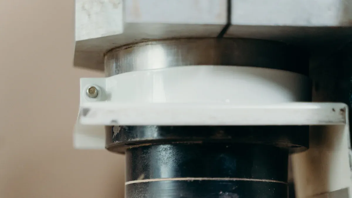
Chuck and Tailstock
The chuck is a crucial component that securely holds the workpiece. It attaches to the spindle in the headstock. Various types of chucks exist, each suited for specific applications:
- Three-Jaw Power Chucks: These are common for gripping round or hexagonal workpieces. They provide balanced clamping for consistent geometry.
- Four-Jaw Power Chucks: These chucks offer independent jaw adjustment. They allow precise centering of irregularly shaped or asymmetrical workpieces.
- Collet Chucks: These use spring-loaded sleeves to grip small-diameter workpieces with high precision. They are ideal for tight tolerances.
- Hydraulic Power Chucks: These use hydraulic pressure for quick, secure clamping and high gripping forces. They suit heavy-duty and high-speed machining.
- Pneumatic Power Chucks: Operating with compressed air, these chucks provide fast clamping. They are suitable for rapid workpiece changes and high production rates.
The tailstock is located at the opposite end of the bed from the headstock. It provides support for longer workpieces. This support prevents deflection and ensures stability during machining operations.
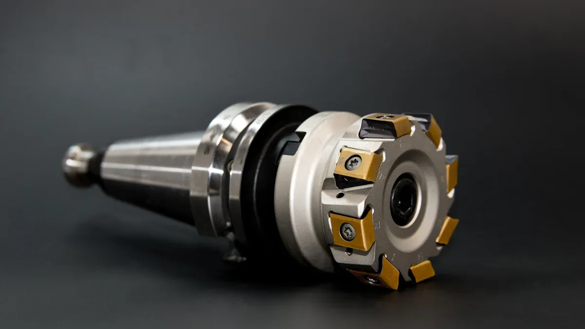
Turret and Cutting Tools
The turret is a multi-station tool holder. It indexes, or rotates, to bring different cutting tools into position. This allows the CNC turning center to perform various operations without manual tool changes. Turrets can hold multiple tools, such as turning tools, boring bars, drills, and threading tools. The machine’s program dictates which tool the turret selects and when. This automated tool changing capability significantly increases efficiency and reduces cycle times.
CNC Controller and Motors
The CNC controller functions as the brain of the entire system. It orchestrates every movement and action within the machine. A CNC control panel provides a group of controls. Operators use these controls to run, store, and edit part program commands and other coordinate information. This allows programs to run in memory mode without constant operator intervention. The Machine Control Unit (MCU) is a powerful computer. It controls and operates the CNC machine, comprising a machine operations panel and a control panel.
The controller performs several critical tasks. It interprets G-code, converting it into precise mechanical actions. It translates G-code into machine commands, including controlling cutting tool movement paths, speed, and feed rates. This ensures the machine follows the exact design specifications. The controller also monitors the machining process. This ensures precision and efficiency throughout the operation. Furthermore, it handles complex instructions and supports multi-axis operations. This capability allows for the machining of intricate parts.
Motors receive these precise commands from the controller. They execute the physical movements of the machine’s axes and the spindle. Most CNC turning centers use servo motors. Servo motors offer high precision and feedback capabilities. They constantly communicate their position back to the controller. This closed-loop system ensures extreme accuracy. Stepper motors are another option, often found in smaller or less demanding applications. They move in discrete steps. The coordinated action of the controller and these powerful motors allows the machine to perform complex cuts with remarkable speed and accuracy.
How a CNC Turning Center Works: Step-by-Step
Design and Programming
The journey of a workpiece through a CNC turning center begins long before it reaches the machine. Engineers first create a detailed digital model of the desired part. They use Computer-Aided Design (CAD) software for this crucial initial step. This software allows for precise geometric definition and visualization of the component. Once the design is complete, the digital model moves to Computer-Aided Manufacturing (CAM) software. This specialized software translates the CAD design into a series of instructions the CNC machine understands.
This translation process generates what engineers call G-code and M-code. These are the fundamental programming languages that guide CNC machines, including turning centers. G-code, also known as RS-274D, primarily dictates the movements of the machine. It tells the machine where to start, how to move the cutting tool, and when to stop. M-code, on the other hand, handles auxiliary commands. These commands control non-geometric functions. Examples include halting the program, activating coolant systems, and powering down the machine. Kevin Finan, an instructor at Atlantic Technical College and Technical High School, emphasizes the importance of these codes. He states that understanding G-code and M-code is fundamental to comprehending machine programming in CNC manufacturing today. Students learn CNC machining using G-code and M-code after mastering manual machining, highlighting their standard use in the industry.
Setup and Tooling
After programming, the machine requires careful physical preparation. This phase involves securing the raw material, known as the workpiece, and preparing the cutting tools. Operators attach turning fixtures to the machine spindle’s nose or a faceplate. These fixtures securely hold the workpiece during the turning process. For certain intricate lathe-made components, a counterweight might be necessary to balance any unevenness. This ensures precision and stability throughout the operation.
Proper fixture setup and alignment are crucial for precise machining. They ensure consistent production quality and minimize errors and rework. Optimizing clamping and holding techniques stabilizes the workpiece. This prevents movement, improves accuracy and surface finish, and preserves workpiece integrity, especially for delicate or complex parts. Operators design fixtures for one-handed operation when possible. This allows them to stabilize parts with the other hand. They also aim for designs that do not require human intervention to hold parts during secondary operations. Simplified designs with minimal steps reduce cycle times and repetitive actions. Choosing geometries that highlight misalignment faults helps reduce workplace injuries. Furthermore, operators carefully select materials for fixtures. For multi-part tools, durable materials like hardened steel are recommended. Alternatives like plastic and wood may suit other applications.
Next, operators select the appropriate cutting tools for the specific operations. They load these tools into the machine’s turret. The turret is a multi-station tool holder. It indexes to bring different cutting tools into position as needed. This automated tool changing capability significantly enhances efficiency.
Program Loading and Operation
With the workpiece secured and tools loaded, the operator loads the generated G-code and M-code program into the machine’s CNC controller. The controller then performs initial checks to ensure all parameters are correct and the machine is ready. Once verified, the operator initiates the machining process.
The CNC controller takes over, interpreting the program line by line. It sends precise commands to the machine’s motors. These motors drive the spindle, rotating the workpiece at the specified speed. They also move the cutting tools along the programmed paths. The cutting tool engages with the rotating workpiece, progressively removing material to achieve the desired shape and dimensions. During this process, the controller continuously monitors various parameters. It checks tool position, cutting speed, and feed rates. This real-time monitoring ensures the machine maintains high precision and efficiency throughout the operation. Regular monitoring helps maintain high precision. It facilitates prompt error detection and correction. This prevents defects, ensuring consistent product quality and enhanced productivity. Implementing safety measures protects operators and equipment. It minimizes downtime and extends the lifespan of fixtures and machines.
Material Removal and Monitoring
As the CNC turning center operates, the cutting tool engages the rotating workpiece. This action precisely removes material layer by layer. The machine follows the programmed tool paths and feed rates. This process gradually transforms the raw material into the desired shape. During this critical phase, continuous monitoring is essential. It ensures the machine maintains accuracy and efficiency. Operators and the machine’s control system actively watch for any deviations.
Effective monitoring involves several key methods:
- Process Monitoring:
- Observing Cutting Load: Modern CNC machines display the force the cutting tool exerts. A steady load indicates stable cutting. Fluctuations can signal issues. These issues include improper chip formation, tool wear, or variations in the material.
- Monitoring Cutting Sound: The sound produced during machining offers clues about process health. Deviations from a normal, consistent sound can point to problems. For example, scraping, chattering, harsh, or squealing sounds suggest dull tools, unstable cutting, or workpiece chatter.
- Workpiece Monitoring:
- Dimensional Accuracy: Operators periodically check workpiece dimensions. They use instruments like calipers or Coordinate Measuring Machines (CMMs). This helps detect discrepancies early.
- Surface Finish: Regular inspection of the machined surface is also important. Operators perform visual checks or use roughness gauges. This helps identify defects like scratches or unevenness. It allows for timely parameter adjustments.
This vigilant monitoring helps prevent defects. It ensures consistent product quality. It also enhances productivity by allowing quick adjustments.
Part Ejection and Cycle Repetition
Once the cutting operations are complete, the machine performs the final step. A cutoff tool separates the finished part from the remaining raw material. After separation, the machine ejects the part. In high-volume production, this process is highly automated. The finished part either drops or an air blast ejects it into a part catcher. This catcher is located beneath the spindle.
Part catchers prevent damage to the finished component. They cushion the part’s fall. Many catchers include a sensor. This sensor confirms the part’s arrival. If a part fails to land in the catcher, the sensor triggers an alarm. This alarm halts production. It prevents potential machine crashes or damage to subsequent parts. The efficiency of this ejection process is crucial for continuous manufacturing.
Typical cycle times for part ejection in high-volume CNC turning are very fast:
| Operation | Cycle Time (seconds) |
|---|---|
| Part Catcher | 1 |
| Part Ejection | 1 |
After the part ejects, the machine prepares for the next cycle. The chuck opens, and an automatic bar feeder advances new raw material. The chuck then closes, securing the new workpiece. The CNC controller loads the program again. The entire machining process repeats. This continuous, automated cycle allows for high-volume production with minimal human intervention. It ensures consistent output and efficiency.
Key Operations of a CNC Turning Center
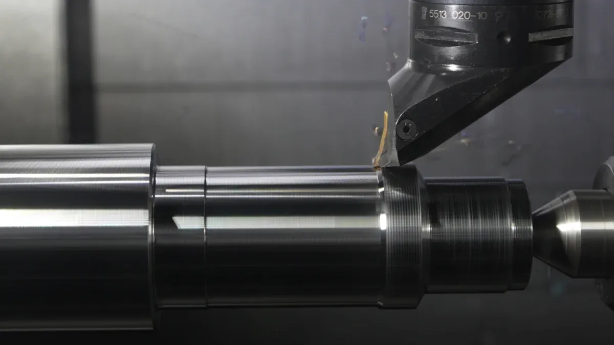
Turning and Contouring
CNC turning centers perform various operations to shape workpieces. Turning is a fundamental process. It involves rotating a workpiece against a single-point cutting tool. This removes material and creates cylindrical shapes. Contouring is a more advanced turning operation. It machines complex curves, contours, and shapes on a workpiece’s surface. This includes manufacturing components with intricate geometries. Examples are camshafts, turbine blades, and custom-designed parts. Tapered turning is another application. It creates precise fits for items like Morse taper shafts and tool holders. Grooving is also a contouring operation. It creates features such as O-ring or circlip grooves.
Boring and Drilling
Boring and drilling are crucial for creating and refining holes in workpieces. Drilling creates initial holes. Boring refines pre-drilled or cast holes to specific tolerances. This is essential for producing components like bushings, bearings, and internal threads. Various tools support these operations. Rough boring heads are designed for performance and versatility. They come in small, medium, and large diameter systems. Fine boring heads offer high-precision finishing for similar diameter applications. Solid boring bars are used for longer-reach applications. Damping bars provide added vibration resistance for these longer reaches. Specialized methods like gun drilling create small-diameter holes with high depth-to-diameter ratios. BTA drilling uses multi-edged tools for larger deep holes.
Grooving and Threading
Grooving operations create channels or recesses on a workpiece. For outer diameter (OD) grooving, the tool tip is held slightly below the center line. For inner diameter (ID) grooving, the tool top is positioned above the center line. In face grooving, the tool is held slightly above the center line and moves axially. The clearance radius on the tool matches the radius being cut. Common techniques involve programming the groove profile, mounting the grooving insert, and cutting in multiple passes for deep or wide grooves. Managing chip evacuation and heat through coolant or pecking is also important. Threading is another turning operation. A tool moves along the side of the workpiece. It cuts a uniform helical groove of a specified length and pitch on the outer surface. Deeper threads often require multiple passes of the tool.
Parting and Cut-off
Parting and cut-off operations represent the final stages in many CNC turning processes. These operations separate a finished component from the raw bar stock or a larger workpiece. A specialized cutting tool, often called a parting tool, moves radially into the rotating workpiece. It creates a narrow groove until it severs the part. This process requires precision to ensure a clean break and prevent damage to the finished component.
Operators prioritize safety during these operations. They implement several critical measures:
- They avoid overly aggressive cutting conditions and insufficient workholding. This prevents machining pressures from exceeding the machine’s or workholding device’s capacity. It ensures both machine integrity and operator safety.
- Operators do not allow a bar to hang out from the spindle. When using bar pullers, the bar never extends past the spindle end at the back of the machine. An unsupported bar can bend violently at high speeds, causing severe machine damage and potential injury.
- Programmers ensure safe rapid approach motion. They use a rapid approach distance, for example, 0.1 inches or 2.5 mm. Operators know how to control the rapid approach moment using features like single block, feed hold, and rapid override. Consistency in programming rapid approach movements also enhances operator safety.
Achieving optimal results in parting and cut-off also involves specific best practices:
- The machine substantially reduces the feed rate as the tool approaches 0.080 inches (2 mm) from the center, potentially by up to 75%. This prevents built-up edge (BUE) formation and insert chipping, especially with hard, wear-resistant grades.
- Operators stop the tool before the center. Feeding past center can cause the part to strike and damage the insert once it breaks free. It can also lead to rubbing action and the part trying to pull the insert out of its pocket. If feeding past center is necessary, the tool does not exceed center plus the insert corner radius.
- For tools with internal coolant, the machine turns off the coolant as the insert nears the center and RPMs are maxed out or decreasing. This prevents the cutting point temperature from dropping too low, which can cause BUE, particularly with wear-resistant grades and stainless steel.
- Operators maintain a reasonable center height. The tool’s center height stays within ± 0.004 inches (0.1 mm). Being too far above center increases rubbing and vibration, leading to chatter and insert breakage. Being too far below center increases cutting forces, risking insert chipping or complete shearing.
- They keep a short overhang. Minimizing tool overhang increases rigidity and security, which is crucial for parting off operations. Excessive overhang leads to vibrations, chatter, and insert breakage. A general recommendation suggests 8 to 10 times the insert width, though specific tools may allow for more.
Advantages of Using a CNC Turning Center
High Precision and Accuracy
Modern manufacturing demands exceptional precision, and CNC turning centers deliver this consistently. These machines achieve remarkable dimensional accuracy, typically ranging from ±0.0001″ to ±0.005″. This level of precision ensures that parts meet exact specifications. Advanced CNC turning centers, particularly those equipped with multi-axis configurations, live tooling, and high-speed automation, can achieve micron-level precision. Industries such as aerospace, medical, and automotive rely on these machines to produce complex parts. Consistency and high precision are critical in these sectors. Advancements like live tooling, Y-axis, and C-axis control have transformed CNC turning into a multi-functional process, enabling these tight tolerances.
Increased Production Efficiency
CNC turning centers significantly boost production efficiency. Their automated operation allows for continuous manufacturing with minimal human intervention. These machines execute complex machining operations quickly and accurately, reducing cycle times. Features like automatic tool changers and robotic part handling further streamline the production process. This automation minimizes downtime and maximizes throughput. Manufacturers can produce a higher volume of parts in less time, leading to increased output and faster delivery to market.
Reduced Labor Costs
The automation inherent in CNC turning centers leads to substantial reductions in labor costs. A single operator can oversee multiple machines simultaneously, as the machines handle most of the operational tasks. This reduces the need for a large workforce dedicated to individual machines. Furthermore, the precision and repeatability of CNC turning centers minimize errors and rework, which also contributes to lower overall production expenses. Companies can allocate their skilled labor to more complex tasks, optimizing human resources.
Complex Geometries and Repeatability
CNC turning centers excel at producing parts with complex geometries. These machines precisely shape intricate designs that manual methods cannot achieve. They create a wide range of sophisticated components. Examples include:
- Complex cylindrical and prismatic geometries
- Shafts
- Hubs
- Rings
- Valve bodies
- Automotive components
- Multi-feature rotational parts
- Complex shafts
- Housings
- Hybrid geometries
The advanced programming capabilities allow for multi-axis machining. This enables the creation of parts with curves, angles, and internal features in a single setup. This capability reduces the need for multiple machines or manual intervention. It streamlines the manufacturing process significantly.
Repeatability is another major advantage of CNC turning centers. Once programmed, the machine executes the same operations with extreme consistency. It produces identical parts every time. This consistency is crucial for mass production. It ensures every component meets the exact specifications. The machine’s ability to repeat precise movements eliminates human error. This leads to uniform product quality across entire production runs. Manufacturers rely on this high repeatability for critical applications. These applications demand strict adherence to design tolerances. This ensures reliable performance and interchangeability of parts. The consistent output minimizes waste and rework. It contributes to overall cost savings and efficiency in manufacturing.
CNC turning centers are indispensable in modern manufacturing. They offer unparalleled precision and efficiency in shaping cylindrical parts. Understanding their components and operational principles highlights their critical role. These machines produce a vast array of products. A CNC Turning Center ensures high quality and consistent output across various industries. This technology drives innovation and productivity.
FAQ
What is a CNC turning center’s primary function?
A CNC turning center precisely shapes workpieces. It rotates the material against a cutting tool. This automated process creates cylindrical parts with high accuracy and repeatability.
How do CNC turning centers differ from manual lathes?
CNC turning centers use computer programs for automated, precise operations. Manual lathes require direct operator control. CNC machines offer superior accuracy, efficiency, and consistency for complex parts and high-volume production.
What types of materials can CNC turning centers machine?
CNC turning centers process a wide range of materials. These include:
- Various metals like stainless steel and superalloys
- Ceramics
- Engineered plastics
What are the main benefits of using a CNC turning center?
Key benefits include high precision, increased production efficiency, and reduced labor costs. They also produce complex geometries with excellent repeatability.
What is G-code in CNC machining?
G-code is the programming language for CNC machines. It instructs the machine on tool movements, speeds, and paths. M-code handles auxiliary functions like coolant activation.
Post time: Jan-07-2026